CONTROLS, INSTRUMENTS AND EQUIPMENT
fmo2014-002-008_a
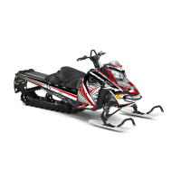
SLIDE TOWARDS FRONT
Upper Body M odule Installation
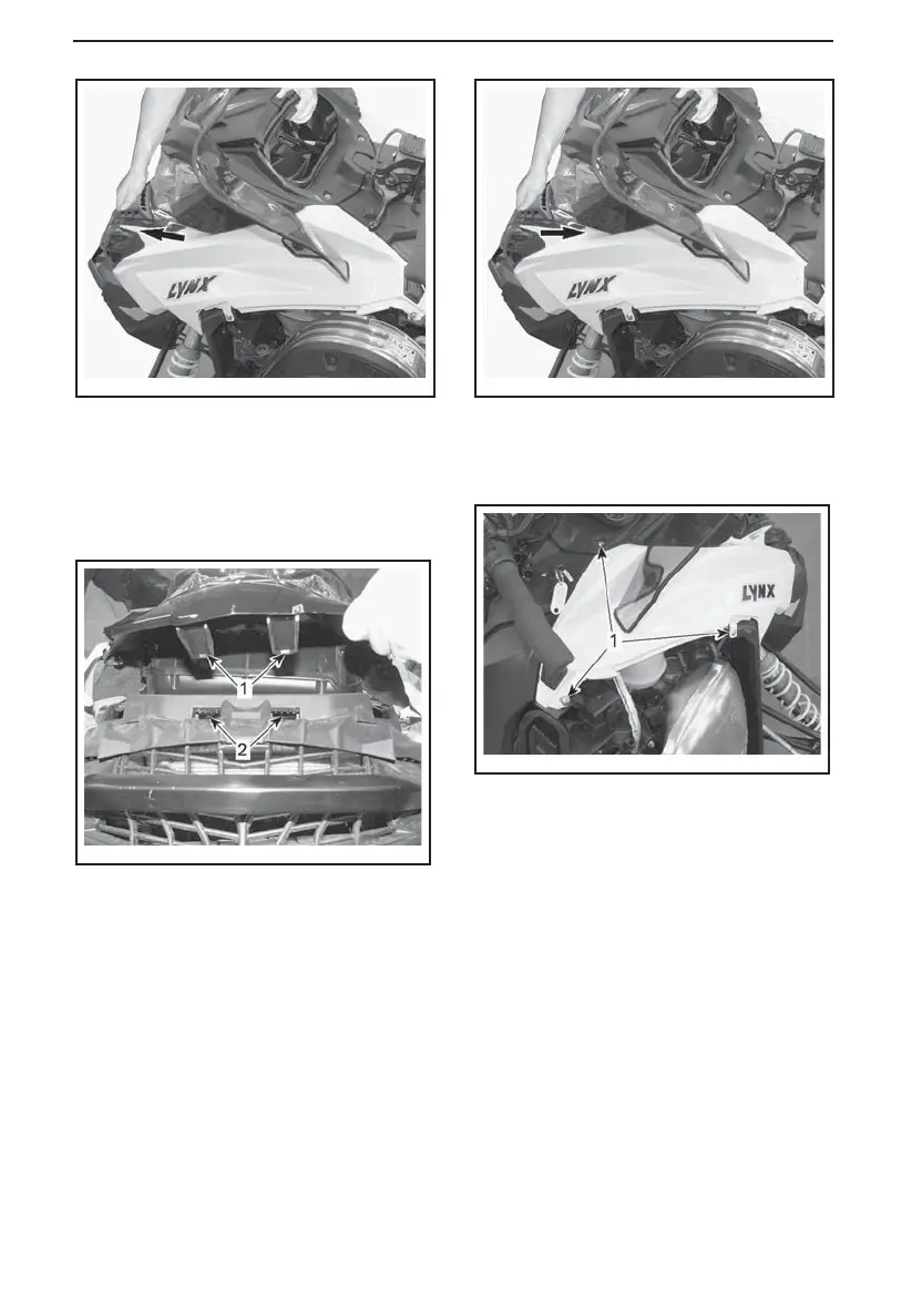
1. Insert the upper body module tabs
into the upper bottom pan open-
ings.
fmo2014-002-004_a
1. U pper body module tab
2. U pper bottom pan opening
2. Slide the module towards rear.
fmo2014-002-008_b
SLIDE TOWARDS REAR
3. On both sides, install the upper body
module retaining screws.
fmo2014-002-005_a
RH SIDE SHOWN
1. Retaining screws
E-TEC Models
4. Connect:
– APS hose on the ECM
– Headlights connector
– Gauge connector
– Air temperature sensor (ATS)
– Air intake connector tube.
ACE Models
5. Connect:
– Headlights connector
– Gauge connector
– Air intake connector tube
.
70
______________
 Loading...