Do you have a question about the Lyrec TR532 Series and is the answer not in the manual?
Detailed technical data for tape speed, reel type, stability, wow/flutter, rewind/start times, accuracy, inputs/outputs, sync, equalization, and bias frequency.
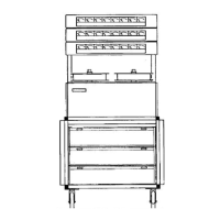
Physical dimensions of the TR532 recorder and its remote control units, shown in diagrams.
Comprehensive list of included accessories and parts for each unit, detailing tools, cables, and connectors.
Overview of the manual's scope, covering description, installation, operation, and service for Lyrec TR532 series recorders.
Detailed description of the TR532 tape deck's compact layout, tape path, speed control, tension maintenance, and front panel controls.
Explanation of the AM77 amplifier design, adjustments, and features like equalization and bias control for plug-in boards.
Description of the VU-meter panel's mounting options and calibration capabilities for studio requirements.
Information on the console's construction, casters, and electrical interconnections for the tape deck and amplifiers.
Features of the remote control unit, including channel switching, SOLO button, VARISPEED, TAPE TIMER, and SEARCH FUNCTION.
Instructions for carefully unpacking the machine, inspecting for damage, and retaining packing materials.
Steps for wiring mains connectors, ensuring voltage compatibility, following local regulations, and connecting other components.
A detailed table listing connector designations, types, mating connectors, and wiring responsibilities for the tape deck and electronics.
Visual representations of connector pin assignments and configurations for various input/output and control signals.
Guidelines for safely transporting the Lyrec TR532 recorder using a car or van, including the use of a special transport frame.
Procedure for powering up the machine, selecting tape speed, and verifying indicator lights and fan operation.
Instructions for loading reels, securing them, and threading the tape through the tape path.
Steps to engage PLAY MODE, including pressing START, observing roller engagement, and selecting REPRO for monitoring.
Guide to selecting channels for RECORD MODE, pressing READY, and engaging RECORD and START buttons for recording.
Instructions for using the FAST WIND mode from both the tape deck and remote control unit.
Procedure for entering EDIT MODE to allow precise spot erasing or listening without tape contact.
How to use the STOP button to halt tape motion and place electronics in standby condition.
Overview of the tape deck's logic design to prevent tape damage and allow smooth transitions between modes.
Explanation of the READY mode for channels, indicating readiness for recording and the LED behavior.
Procedure for pre-selecting tracks to drop in or out of record mode without interrupting tape motion.
Explanation of the SAFE mode function for preventing channels from entering RECORD MODE, including master and individual SAFE buttons.
How to select LINE, SYNC, or REPRO signals for output from playback amplifiers.
Function of the SOLO and DEFEAT buttons for isolating or muting individual channels.
How the TAPE TIMER displays elapsed time and how to reset it.
How to use the SEARCH FUNCTION with a PRESET DIAL to locate specific tape positions accurately with no overshoot.
Details on using NOMINAL and VARISPEED buttons, including speed adjustments and using the TAPE TIMER for speed checking.
Information on the separate sync amplifier and its output for each channel.
Overview of special features like HEADBLOCK, EDITING FACILITIES, SWITCH-OFF SAFE-GUARD, SPEED MEMORY, and TRANSIENT PROTECTION.
Description of the TPC unit, its four-digit display, memory functions, and search capabilities for precise tape positioning.
Procedures for adjusting reel platform height, tension arm pressure, and pinch roller pressure for optimal tape transport.
Instructions for adjusting guide roller pressure to specific force values for proper tape guidance.
Steps for adjusting rollers to be perpendicular to the tape deck using set screws and an alignment template.
Procedure for adjusting the upper capstan bearing point to ensure correct contact and minimum motor current.
Setting the tension for mechanical brakes to ensure servo-arms don't reach rest position prematurely.
Critical adjustments for tape path alignment, including reel platform height, guide roller height, and perpendicularity.
Detailed steps for fine-tuning head azimuth using an oscilloscope and test tape for optimal signal alignment.
Procedures for adjusting the AM77 amplifiers for correct frequency response, including playback level, sync, and bias settings.
Steps to adjust bias current and resonance for optimal record/playback performance and to minimize bias leakage.
Procedure for setting record levels and ensuring a flat frequency response across different frequencies.
Steps to adjust erase current for symmetry and optimal low-frequency noise reduction.
How to adjust VU-meter levels to match studio metering systems using a test tape or tone source.
Procedures for adjusting bias filters and DC currents in amplifier circuits, typically only needed after component replacement.
Explains the operational principles of the capstan motor system, speed preamplifier, and frequency detector.
Details on how the capstan motor is braked to prevent tape loops during start/stop operations.
How acceleration time and run quality in nominal speed are controlled via potentiometers.
Explanation of the motor control commutator's function, signals from Hall generators, and overspeed trigger circuit.
Description of the servo system controlling the supply and take-up motors, including voltage sources and logic information.
How the wind speed limit circuit prevents excessive tape winding speeds and controls tape tension.
How dynamic braking is achieved through opposite direction wind functions and logic from the tachometer.
Operation of solenoids for capstan and guide rollers, including pull and hold-on voltages and timing during start/stop.
How the muting system operates to protect speakers and its interaction with STOP, START, and EDIT controls.
Recommended daily procedure for demagnetizing tape heads and metal parts to prevent noise and distortion.
Information on the ventilation fans, air filters, cleaning, and checking filter status.
Specific lubrication points for the capstan top bearing, glass air cylinders, and solenoid plungers.
Step-by-step instructions for safely removing the head block assembly from the tape deck.
Procedure for replacing the tension arm potentiometer, including accessing and disassembling the clutch assembly.
Recommended monthly checks including visual inspection, tape transport modes, and playback/sync amplifier performance.
List of special tools required for maintenance and adjustments, including alignment templates and tension measuring devices.
Detailed list of spare parts for the tape deck, control section, and amplifier cabinets, organized by drawing number.
How to achieve phasing, flanging, and doubletracking effects using SYNC OUTPUTS and another tape recorder.
Modification to allow playback signal during winding, useful for time code recording.
How to modify the SOLO function to mute other channels instead of switching them to LINE IN.
Table for aligning CCIR or NAB equalization using test tapes, providing relative output levels.
Procedure to reduce hum by changing a resistor value in the power stabilizer assembly.
Remedy to reduce click-noise by installing capacitors across base emitters of line drivers.
Modification to improve the start-up characteristic by adjusting the START POWER circuit.
Detailed steps for modifying the Code 1 servo system print to improve start-up characteristic.
Solution for slow speed response by adjusting a filter capacitor and connections in the capstan motor control.
Remedy to increase reliability by soldering wires to AMP crimp-connectors, especially for power supply.
Improvement to increase tape timer lamp lifetime by modifying the controlling circuit on the tachometer logic print.
Method to reduce crosstalk by modifying PCB wiring and using shielded cable for the SYNC OUT output.
Remedy to suppress mains transients causing unwanted mode switching by installing filter capacitors on regulators.
Information on new brake bands, their installation, running-in procedure, and adjustment of servo springs.
Guidance on substituting the MJE 2955 transistor with MJE 2955T, noting pin reversal and thermal contact.
Diagram showing head assembly and electronic connection numbers for TR532.
Diagram related to the TR532 tape deck, likely a block diagram or layout.
Schematic diagram for the Capstan motor control circuit, detailing components and connections.
Component location diagram for the Record-Playback Amplifier AM77.
| Brand | Lyrec |
|---|---|
| Model | TR532 Series |
| Category | Measuring Instruments |
| Language | English |