Publication: MAN3002G MAC Equipment, Inc. 20
Header Assembly
1
2
3
5
6
7
9
12
14
13
15
4
Number Part Number Description
1 - - - - - - Header (4” schedule 40 pipe)
2 Diaphragm Valve
3 - - - - - -
Fittings: 90 1/4 x 1/8 brass
4 - - - - - - 1” I.D. hose
5 - - - - - - 1” hose clamps
6 - - - - - - 3/4” x 3” pipe nipple T.O.E.
7 - - - - - - 3/4” NPT air inlet
9 - - - - - - Timer Control Assembly (see
detailed drawing next page)
12 - - - - - - 5/16” - 18 x 1” hex head bolt
13 - - - - - - 5/16” lockwasher
14 - - - - - - 5/16” 18 hex nut
15 - - - - - - Control panel mounting plate.
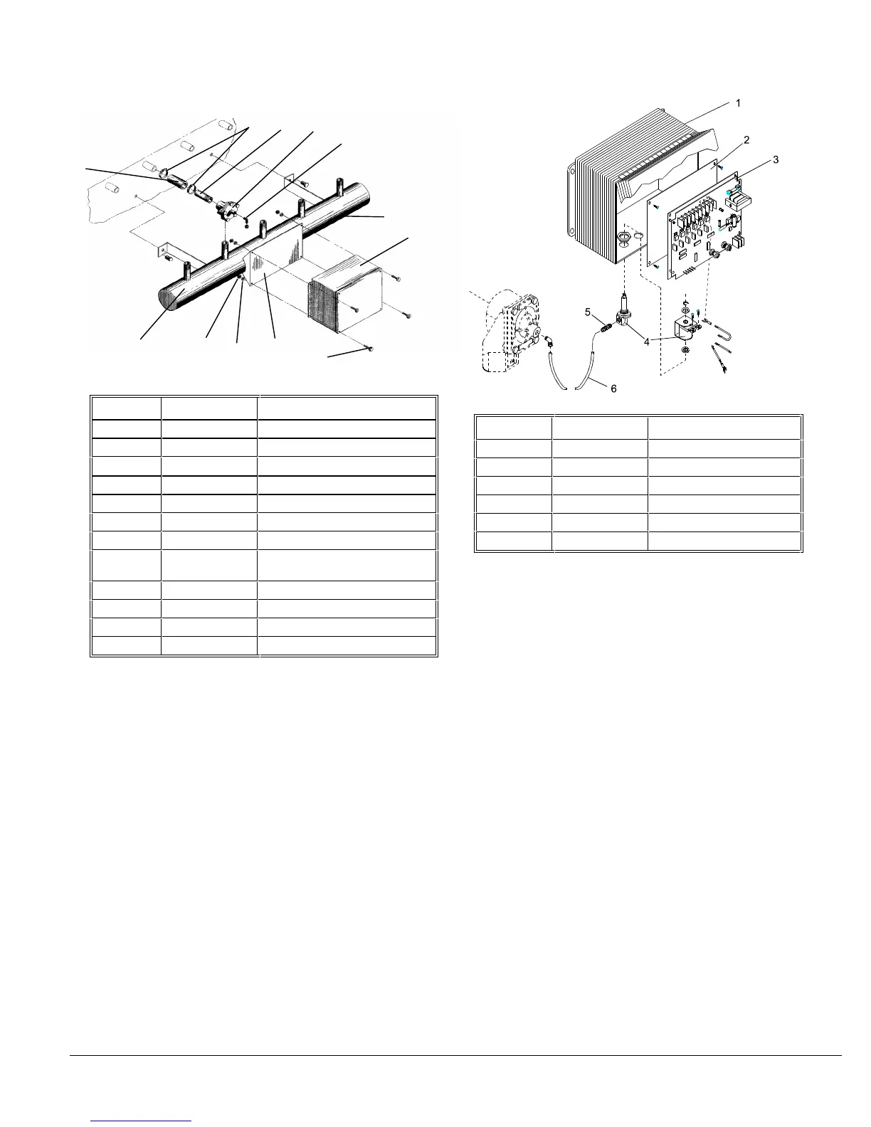
Timer Control Assembly
Number Part Number Description
1 - - - - - - Enclosure
2 - - - - - - Back Panel
3 Timer Control
4 Solenoid Valve
5 - - - - - - Fitting - 1/4 x 1/8 brass
6 - - - - - - Hose, 1/4” 44NF Poly-Flo