Do you have a question about the Macherey-Nagel URYXXON 500 and is the answer not in the manual?
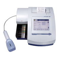
Explains the system's measuring and functional principles and components.
Lists technical specifications including size, weight, power, and operating conditions.
Warns to use only the included power pack and ensure protective grounding for safe operation.
Advises using protective gloves due to urine and test strip risks of infection.
States that misuse or use by untrained staff voids the instrument's warranty.
Instructs to stop use and replace the power pack if a cable breaks to prevent electric shock.
Details environmental requirements for instrument placement and optimal operation.
Step-by-step guide to inserting the transport rack before initial power-on.
Emphasizes using the correct power supply and connecting to grounded outlets.
Explains the various ports for connecting devices and LIS to the instrument.
Details how to power on the instrument and what happens during the initial self-test.
Guidelines for using the touch screen interface, avoiding sharp objects.
Explains interface elements like activity-buttons, option-fields, edit-buttons, and input menus.
Configure units and parameter display order for strips.
Configure communication settings for data transfer and LIS connection.
Options for entering and managing sediment parameters for results.
Turns the sediment entry function on/off and allows editing parameters.
Activates filter criteria to select results for sediment information entry.
Configure access rights and user administration modes.
Sets up one administrator with access to instrument settings.
Allows up to 10 users with individual passwords and administrator rights.
Procedures for creating, editing, and deleting user accounts.
Allows entering sediment findings for displayed results using microscope observations.
Displays all measurements saved in the instrument's memory.
Initiates quality control measurements with positive and negative control solutions.
Measures a colored control strip for equipment monitoring.
Describes creating and using a worklist for batch processing of samples.
Initiates measurements with positive and negative control solutions.
Measures a colored control strip for equipment monitoring.
Explains error codes, their causes, and corrective actions.
| Category | Medical Equipment |
|---|---|
| Display | LCD |
| Product Type | Urine Analyzer |
| Test Principle | Reflectance photometry |
| Interfaces | RS232 |
| Number of Tests | Up to 11 parameters |
| Shelf Life | According to strip type |