Do you have a question about the Maersk Container Industry Star Cool SCU-40 and is the answer not in the manual?
| Weight | Approx. 4, 500 kg |
|---|---|
| Temperature Range | -30°C to +30°C |
| Width | 2.438 m (8 ft) |
| Refrigerant | R134a or R513A |
| Refrigeration Capacity | 7.5 kW at -18°C |
Describes the 5 modes of the unit's start-up sequence.
Explains the container temperature control modes (Chill and Frozen).
Details how the unit controls capacity and the different limiter types.
Illustrates accepted volt/Hz range and alarm set-off values.
Explains the function of the expansion valve and its sub-functions.
Describes the economizer valve's function and control modes.
Explains the dehumidification function and its operating modes.
Details the condenser fan control and its modes.
Explains the evaporator fan control modes (Normal and Economy).
Describes the evaporator defrosting function, initiation, and execution modes.
Defines how the system reacts to defective sensors.
Explains the unit's datalogging capabilities and data retrieval.
Describes the unit component test procedure and its items.
Lists the test items included in a Full Pre-Trip Inspection.
Lists the test items included in a Short Pre-Trip Inspection.
Lists the test items included in a Controlled Atmosphere Pre-Trip Inspection.
Specifies the refrigerant charge amount.
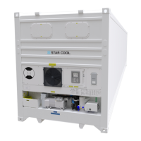
Provides general specifications like weight, dimensions, and noise.
Details the compressor and motor assembly specifications.
Lists specifications for the frequency converter.
Details the specifications of the evaporator coil.
Lists specifications for the evaporator coil heaters.
Details specifications for the evaporator fan.
Lists specifications for the evaporator fan motor.
Details specifications for the condenser coil.
Lists specifications for the condenser fan.
Details specifications for the condenser fan motor.
Provides specifications for the optional water-cooled condenser.
Details fresh air exchange capabilities.
Lists specifications for the air exchange motor.
Details specifications for the economizer.
Lists components related to refrigeration controls.
Details specifications for the vacuum pump and heating element.
Provides electrical specifications for the unit.
Specifies the circuit breaker details.
Lists specifications for the contactors.
Details the high pressure cut out switch specifications.
Specifies the fusible plug details.
Lists fuse specifications.
Details the power plug specifications.
Specifies the power cable details.
Details the USDA socket requirements.
Lists specifications for the O2 sensor.
Details specifications for the CO2 sensor.
Specifies temperature sensor details, including USDA.
Lists specifications for the relative humidity sensor.
Details specifications for the CA pressure transmitter.
Lists specifications for pressure transmitters.
Lists miscellaneous components and specifications.
Explains the function of the alarm and in-range indicator lights.
Describes the unit display layout and icons.
Details the keypad layout and navigation keys.
Describes the layout of the main operation screen.
Explains how to navigate menus using the cursor.
Details the process of changing parameter values.
Explains how to activate functions via the menu.
Describes the air exchange display page.
Outlines the hierarchical structure of the unit's menus.
Provides a general description of operating menus and editing parameters.
Explains how to adjust the temperature setpoint.
Describes the unit's wake-up mode and battery operation.
Explains how to adjust the display contrast and brightness.
Details how to switch between Celsius/Fahrenheit and Bar/Psi units.
Explains how to view temperature graphs.
Details how to activate and deactivate water-cooling.
Guides on how to initiate and perform PTI or Function tests.
Explains how to access and use the information menu.
Describes how to view raw, unfiltered sensor values.
Covers setting key operation parameters like setpoint and control mode.
Introduces the different operating programs available.
Explains the MTS program for changing setpoints at intervals.
Details the ACT program for cargo treatment.
Explains the Bulb mode functionality and settings.
Covers application-specific settings.
Explains the AV/AV+ application for regulating container atmosphere.
Details the CA application for controlled atmosphere.
Guides on initiating manual defrost cycles.
Explains the alarm system, levels, and handling.
Covers access to service functions and sub-menus.
Details how to manually operate unit components.
Explains how to perform a self-test on the frequency converter.
Describes how to view logged datalog information.
Explains how to adjust the unit's date and time settings.
Describes how to view operational run time counters.
Covers unit configuration settings.
Explains the StarConomy energy-saving function.
Lists serial numbers for various unit components.
Details functions related to USB connectivity.
Covers maintenance procedures.
Describes modem settings and status.
Specifies general requirements for serial port setup.
Defines terms related to external interfaces.
Provides an overview of functions supported by different interfaces.
Provides a comprehensive list of all unit alarms with descriptions.
Details the procedure for replacing the evaporator motor and fan.
Details the procedure for replacing the condenser motor and fan.
Describes the steps for replacing the evaporator.
Outlines the procedure for replacing heating elements.
Details the procedure for replacing the Frequency Converter (FC).
Explains the procedure for replacing the compressor.
Details replacing compressor valve plate and head gasket.
Outlines the procedure for replacing the filter dryer.
Describes the procedure for evacuating refrigerant from the unit.
Explains compressor pump down and operation procedures.
Details pump down procedure for a replaced compressor.
Outlines the procedure for pumping down the entire unit.
Describes the procedure for performing a pressure test on the piping system.
Details how to charge refrigerant into the unit.
Explains the process for charging an empty unit.
Details how to charge refrigerant when the unit is low.
Explains methods for detecting refrigerant leaks.
Covers compressor maintenance.
Details how to check the compressor oil level.
Explains how to drain oil from the compressor.
Details how to add oil to the compressor.
Provides guidelines for soldering components.
Outlines precautions for welding on the unit.
Describes how to vent the container for CA operations.
Details the service procedure for the vacuum pump.
Provides steps to troubleshoot vacuum system faults.
Outlines replacing the vacuum pump heating element.
Details the preparation steps for CA operation.
Describes how to install the CA curtain track.
Details the procedure for installing the CA curtain.
Explains how to perform a container leak test.
Describes the CA+ flushing process with nitrogen and CO2.
Explains how to bypass the Frequency Converter (FC).
Details FC bypass procedure for versions 1.0 and 1.1.
Details FC bypass procedure for version 2.0.
Explains how to bypass a defective controller.
Details bypassing a defective evaporator fan motor.
Explains datalog loggings and retrieved data.
Provides a table correlating temperature sensor resistance to temperature.
Provides a table correlating temperature sensor voltage to temperature.
Voltage table for 35 CMH air exchange sensor.
Voltage table for 75 CMH air exchange sensor.
Voltage to pressure table for LP transmitter (NSK) + DST.
Voltage to pressure table for LP transmitter (AKS).
Voltage to pressure table for HP transmitter (NSK) + DST.
Voltage to pressure table for HP transmitter (AKS).
Pressure-temperature table for R134a refrigerant.
Pressure-temperature table for R513A refrigerant.
Lists tightening torques for various fasteners and components.
Piping and Instrumentation diagram of the refrigeration unit.
Functional overview of CA system in two versions.