Page 4 of 18 507388-01Issue 1504
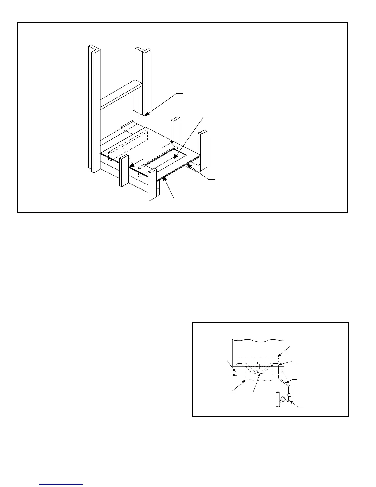
Figure 1
HWC Installaon
Plywood
2
8
" Mi
n
.
Wall Sleeve
Vibration Isolating Material
FLO
O
R
6 x 22 Minimum Opening
to Align with Return Air
Opening in Unit.
""
Figure 2
HWC Evaporator Condensate Drain Installaon
Drain Pan
Open Drain Trap
Return
Air Duct
To Open
Drain Trap
Alternative
Method
5/8
" I .D.
Plastic Tube
(Supplied)
Top of Drain Tube
Must be Below
Bottom of Drain Pan
Drain Tube - Pitch 1"
for every 10 ft.
(Field Supplied)
Evaporator Condensate Drain
Install the plasc drain tube (furnished) over the 5/8” O.D. ng
in the center of the Evaporator condensate pan. Connect other
end of the drain tube to the open trap (see Figure 2). The plasc
drain connecon is provided so that it may be disconnected from
the permanent drain tubing in the building in the event it becomes
necessary to remove the cooling chassis assembly.
The drain line should pitch gradually downward at least 1” per
10’ of horizontal run to the open drain trap.
Be certain that the plasc drain tube has free drainage and is not
crimped or aened at any bend.
Seal the space between the wall sleeve and the building opening
with non-hardening caulking compound. The seal must be
weatherght to prevent entrance of moisture and water into
the building.
Assure that the unit is completely seated against the gaskets on
the wall sleeve.
Installing Without a Wall Sleeve
Refer to the following direcons and Figure 1 for guidance in
installing the unit without a wall sleeve:
1. Measure the size of the unit and provide an opening in an
outside wall that will accept the unit. Local ordinances may
require a steel lintel to support the wall above the opening.
The opening must be square in all four corners.
2. Posion the unit so that the grilles on the outside face of the
unit are ush or extend beyond the face of the exterior wall,
but not recessed more than 2” from the face of the building.
Provide a support under the unit, inside the building. Make
sure that the inside support does not block the return air.
The unit should be installed level or pitched slightly to the
outside of the building so that rain water will drain away.
3. Seal the space between the unit and building opening using
a non-hardening caulking compound. The seal must be
weatherght to prevent entrance of moisture and water into
the building. Make sure the drain holes in the base are not
plugged with caulking.
COMBUSTION AIR
This unit is a direct - vent furnace which obtains all air needed
for combuson from outdoors.
 Loading...