Page 7 of 18507388-01 Issue 1504
edion) for installaons in the U.S. or the Canadian Electrical
Code Part 1, CSA C22.1 (latest edion) for installaons in Canada.
See rang plate for correct wire ampacity for the cooling chassis
required, and size wire accordingly.
Thermostat
Install the thermostat according to the direcons furnished with
it. The thermostat must be located on an inside wall where it will
not be aected by dras, sunlight, or any other heat producing
appliances. Connect the thermostat wires to the low voltage
leads on top of the unit following the wiring diagram aached
to the unit. The heat ancipator seng is 0.50 amp.
Air Filter
All indoor return air must be ltered. A permanent-type lter is
furnished with the unit, located directly behind the access panel.
Removing the panel permits access to the lter. See Figure 3.
If an installaon is made in which it is more desirable to mount the
lter exterior to the unit, in the return duct work or elsewhere, the
permanent lter can be used or replaced with a disposable lter.
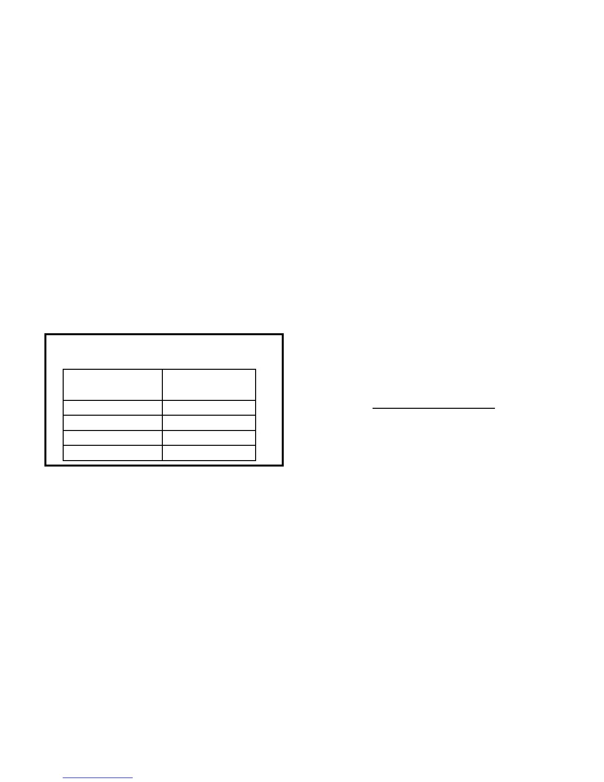
If a disposable lter is used, refer to the informaon provided in
Table 1 when sizing the disposable lter.
Supply and Return Duct(s)
Provide duct(s) sized suciently to handle the larger of the air
volumes for heang or cooling provided by this model.
Connect the supply duct to the top of the unit using canvas
connections or other flexible connections to prevent noise
transmission into the duct system.
To connect the return duct to the system, use a straight piece
of duct 22” wide by 6” deep. Insert the duct into the return
opening in the boom of the unit and ange the duct over the
exisng anges around the opening inside the unit. Make sure
that all sides of the duct are anged over to permit removal of
the cooling chassis if required. Use a exible connecon to aach
the remainder of the return duct. The return duct should be
sealed to the unit casing and must terminate outside the space
containing the furnace.
x
3600
x
=
Cubic Feet Per RevoluonBTU/HR
INPUT # Seconds Per Revoluon
Heang
Value
Adjustments – Heang Secon
Temperature Rise
At me of installaon, the temperature rise must be adjusted to
be within the range specied on the unit rang plate. See table 2.
Pressure Regulator
he gas input must not exceed the gures shown on the rang plate.
The unit is equipped for rated inputs with manifold pressures of:
3.5” W.C. for natural gas and 10.5” W.C. for propane.
The manifold pressure can be measured by removing the pipe
plug in the automac gas valve. Connect a water manometer and
measure the pressure.
Only small variaons in gas input may be made by adjusng the
regulator. In no case should the nal manifold pressure vary
more than 0.3” W.C. for natural gas or 0.7” W.C. for propane.
To adjust the regulator, turn the adjusng screw on the regulator
clockwise to increase pressure and input or counterclockwise to
decrease pressure and input.
For natural gas installaons, check the burner rate by observing
the gas meter (making sure that all other gas appliances are
turned o). The test hand on the meter should be med for
at least one revoluon. Note the number of seconds for one
revoluon.
Adjustments – Cooling Secon (HWC models)
No adjustments are required or should be aempted regarding
any of the components of the cooling chassis. The chassis should
be checked to see that none of the wiring is loose or missing.
Cooling chassis is charged with R410A refrigerant.
Pressure Regulator
Model
Number
Filter Area
(sq. in.)
HWC8-12 300
HWC8-18 480
HWC8-24 480
HWC8-30 480
Minimum Required Surface Area
for Disposable Filters
Table 1
 Loading...