Do not screw into the side of the drain pan, or into the
indoor coil.
Air Filter
All indoor return air must be filtered. A washable filter is
furnished with the unit, located in the return air opening. If
return duct is installed, provisions must be made to
accommodate filter servicing.
The filter should be cleaned at least three times during
each of the heating and cooling seasons, or more fre-
quently if unusual conditions are encountered. To clean
the washable filter, shake filter to remove excess dirt
and/or use a vacuum cleaner. Wash filter in soap or
detergent water and replace after filter is dry. It is not
necessary to oil the filter after washing.
If an installation is made in which it is more desirable to
mount the filter exterior to the unit, in the return duct work
or elsewhere, the washable filter can be used or replaced
with a disposable filter. If a disposable filter is used, use
the information provided in Table 4 when sizing the
disposable filter.
Minimum Required Surface Area
for Disposable Filters
MGE*12 192 square inches
MGE*18 288 square inches
MGE*24 384 square inches
. I
MGE 30 480 Square inches
10 and 12 SEER models
Table 4
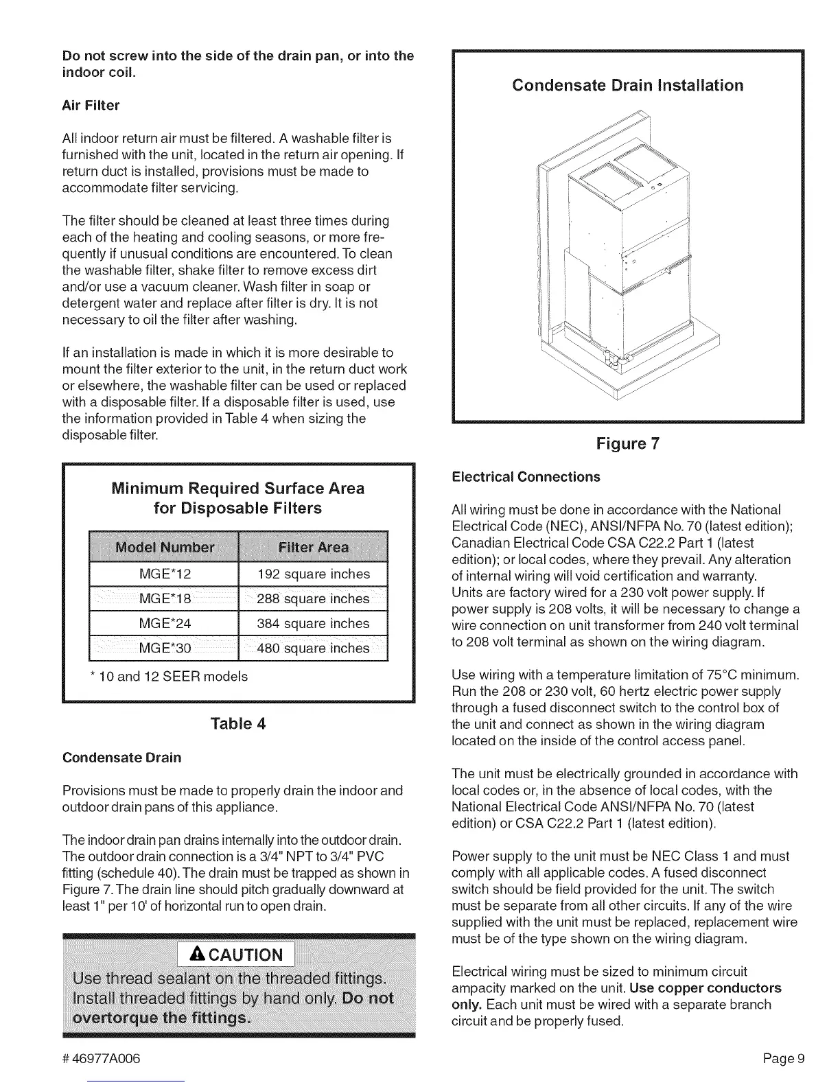
Condensate Drain
Provisions must be made to properly drain the indoor and
outdoor drain pans of this appliance.
The indoor drain pan drains internally into the outdoor drain.
The outdoor drain connection is a 3/4" NPT to 3/4" PVC
fitting (schedule 40). The drain must be trapped as shown in
Figure 7.The drain line should pitch gradually downward at
least 1" per 10' of horizontal run to open drain.
Condensate Drain Installation
Figure 7
Electrical Connections
All wiring must be done in accordance with the National
Electrical Code (NEC), ANSI/NFPA No. 70 (latest edition);
Canadian Electrical Code CSA C22.2 Part 1 (latest
edition); or local codes, where they prevail. Any alteration
of internal wiring will void certification and warranty.
Units are factory wired for a 230 volt power supply. If
power supply is 208 volts, it will be necessary to change a
wire connection on unit transformer from 240 volt terminal
to 208 volt terminal as shown on the wiring diagram.
Use wiring with a temperature limitation of 75°C minimum.
Run the 208 or 230 volt, 60 hertz electric power supply
through a fused disconnect switch to the control box of
the unit and connect as shown in the wiring diagram
located on the inside of the control access panel.
The unit must be electrically grounded in accordance with
local codes or, in the absence of local codes, with the
National Electrical Code ANSI/NFPA No. 70 (latest
edition) or CSA C22.2 Part 1 (latest edition).
Power supply to the unit must be NEC Class 1 and must
comply with all applicable codes. A fused disconnect
switch should be field provided for the unit. The switch
must be separate from all other circuits. If any of the wire
supplied with the unit must be replaced, replacement wire
must be of the type shown on the wiring diagram.
Electrical wiring must be sized to minimum circuit
ampacity marked on the unit. Use copper conductors
only. Each unit must be wired with a separate branch
circuit and be properly fused.
#46977A006 Page9
 Loading...