Do you have a question about the Magtech LTM-300 Series and is the answer not in the manual?
The LTM-300 is an electronic field instrument for hazardous and non-hazardous industrial areas.
Describes single-purpose float setup for measuring liquid level.
Explains accessory use with gages and standalone installation.
Details the Sensor Tube Assembly and Electronics Housing components.
Explains the magnetostrictive principle and distance computation.
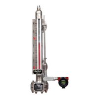
Instructions for mounting transmitter to MagTech LG series level gage.
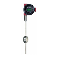
Details installation of the standalone unit with a compression fitting.
Lists supply voltage, repeatability, non-linearity, accuracy, and output.
Details material, operating temperature, pressure, and range.
Describes three configurations: single, level+interface, level+temp+interface.
Options for measurement display, units, model, sensor length, PV, and alarm settings.
Procedures for range change, damping, sensor/DAC calibration, and loop tests.
Troubleshooting common calibration problems and erratic output.
Addressing problems caused by magnetic bias or residual energy.
Troubleshooting power supply issues and gage-mounted start-up.
Details the warning label regarding insulation and temperature limits.
Outlines the product warranty terms and conditions.
Information regarding the HART protocol option.
Introduces HART communicator screens and user interface.
Navigating through device setup menus like Basic, Detailed, and Review.
Viewing process variables and accessing diagnostics and service menus.
Checking operational and calibration status bits for issues.
Viewing abnormal conditions and resetting maintenance flags.
Procedures for resetting maintenance flags and performing loop tests.
Selecting the specific calibration type to perform.
Calibrating the 4-20mA output using a reference meter.
Procedures to set transmitter output to 4mA and 20mA for calibration.
Zero Level Trim and Full Level Trim for measuring liquid level.
Zero Temperature Trim for RTD reference value.
Trimming temperature at reference and upper end points.
Changing 4mA/20mA values and units via keypad.
Setting 4mA/20mA points by vessel level/interface.
Selecting Level or Interface as the primary variable controlling loop current.
Changing the unit of measure for Level/Interface.
Modifying Lower/Upper Range Values using keypad input.
Sending modified range values to the transmitter.
Accessing Unit code, Probe Length, and Sensor Trim options.
Modifying damping factor and configuring Analog/HART outputs.
Viewing distributor, model, tag, and revision numbers.
Viewing or editing the probe length parameter for diagnostics.
Setting a 4mA point reference from the probe end.
| Brand | Magtech |
|---|---|
| Model | LTM-300 Series |
| Category | Transmitter |
| Language | English |