29
LOADER INSTALLATION
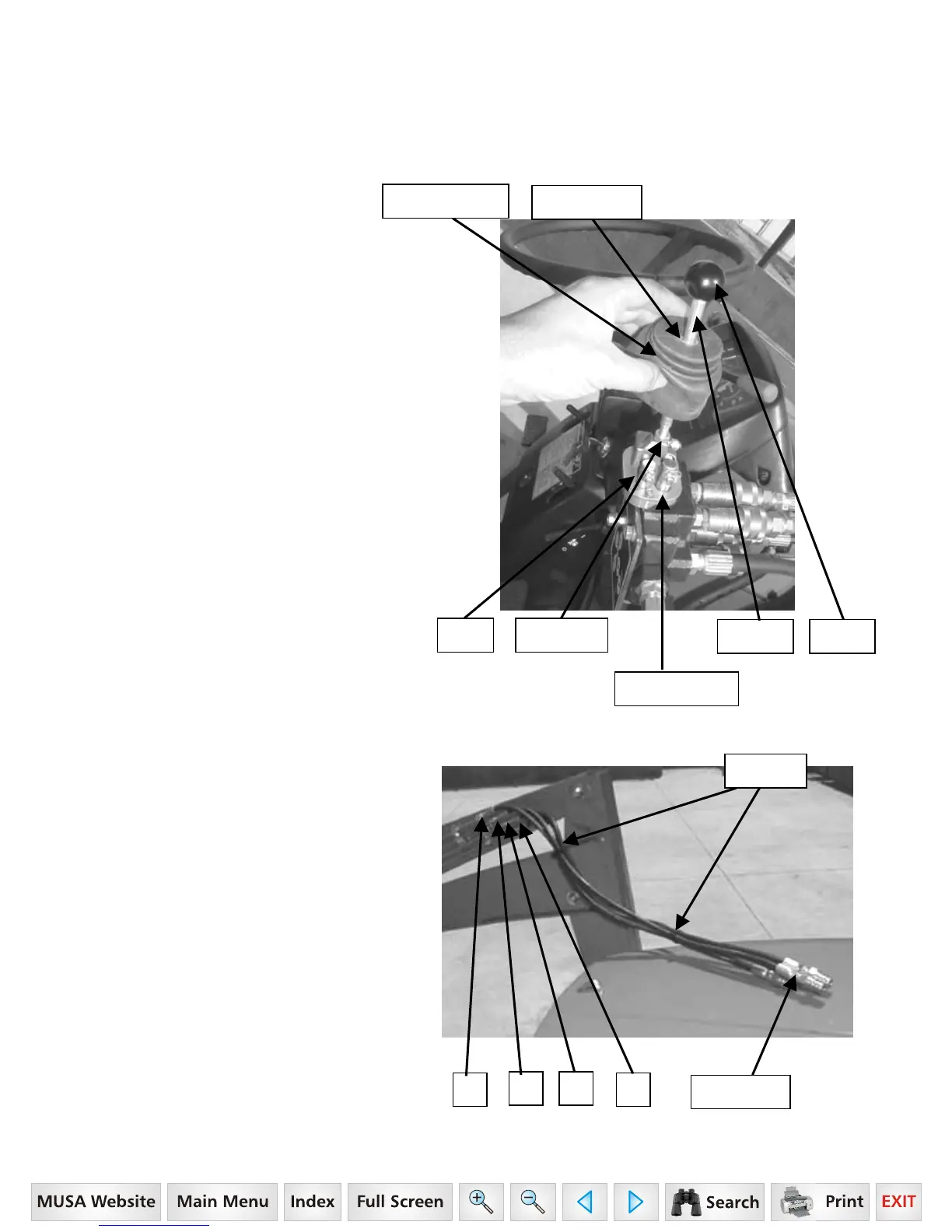
STEP 9. Install Handle and Rubber Boot to
Single Lever Control Kit (SLC) as follows:
1. Thread Lock nut and slide washer onto
handle.
2. Screw handle onto SLC.
3. Tighten lock nut.
4. Position Rubber Boot over handle and
onto SLC.
5. Position Boot Guide over Handle and
into rubber boot and secure boot by
positioning it over boot mount.
6. Thread Knob onto end of handle.
STEP 10. Attach 9/16” JIC male end of
1/4” x 40” hydraulic hose to loader tubing.
Mark the quick coupler end of each hose
with colored nylon ties of individual color as
noted below.
1. Red – top line.
2. Yellow – 2
nd
line from top.
3. Green – 3
rd
line from top.
4. Blue – bottom line.
Bundle hoses together and secure as
shown using nylon ties provided with loader
kit.
1
2 3
4
Color ties
SLC Lock Nut
Knob Handle
Rubber Boot
Rubber Boot
Boot Guide
Secure
16 Series, Model - 2816
 Loading...