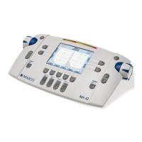
Operating Instructions MA 41
8100456_OI_MA41_EN_15a 5 8100456-8 04/15
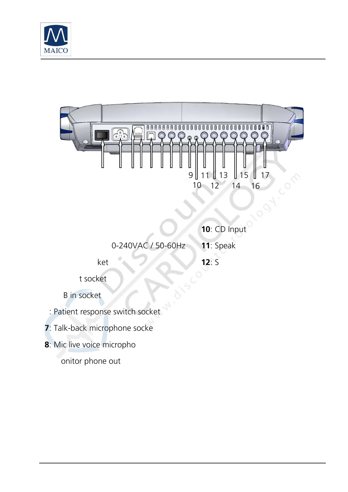
3.4 Rear Panel Connections
Figure 1– Rear View of the MA 41
: Power switch
: CD Input
: Power socket 100-240VAC / 50-60Hz
: Speaker left channel
: Network socket
: Speaker right channel
: USB out socket
: Bone conduction receiver
: USB in socket
: Insert phone left channel
: Patient response switch socket
: Insert phone right channel
: Talk-back microphone socket
: Phone left channel
: Mic live voice microphone socket
: Phone right channel
: Monitor phone output socket
Place the MA 41 on a stable counter or table. Plug the power cord into the
power socket on the rear panel. Connect all accessories with the appropriate
sockets as shown above. Plug the power cord into a grounded outlet.
Turn on the instrument with the power switch, which is located on the rear
panel of the MA 41. The device will perform its initialization and boot up. Please
wait until the test screen appears, this can take up to 60 seconds. If an error is
11
13
14
16
15
12
10
1
17
 Loading...