Do you have a question about the Maico MC 250 and is the answer not in the manual?
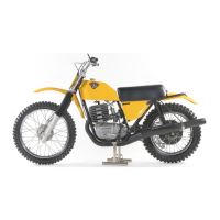
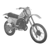
Detailed description of the engine components including cylinder, head, piston, crankshaft, primary drive, ignition, clutch, gearbox, and exhaust system.
The cylinder is a special moto-cross cylinder constructed of a light alloy material with a shrunken cylinder sleeve. The cooling fins are arranged radially for better cooling even at low speeds. The cylinder is fastened to the crank cases by four 8 x 28 mm studs. Between the cylinder and main cases is a paper gasket 0.3 mm thick.
Is also constructed of a light alloy material. The cooling fins are again arranged radially with five - 8 mm or 10 mm studs mounting it to the cylinder. The cylinder head gasket is made of soft copper (0.6 mm thick).
The MAHLE piston is forged of a special piston alloy containing a large amount of silicon. With "L" shaped piston ring in the 250, 440 and 501. An "L" shaped and a rectangular piston ring is used in the 400. The piston clearance in the cylinder measures 0.05 to 0.07 mm.
The crankshaft halves are turned on a lathe from rough forgings. After careful machine finishing, they are heat treated for better case hardening. The right half or magneto half is tapered. The left half has a key way or splines to attach the primary drive sprocket.
The primary drive from the crankshaft to the clutch is by means of a double-row chain 3/8" x 7/32" in the MC 250 and a triple-row chain 3/8" x 7/32" in the 400, 440 and 501. The chain is an endless type and has 54 links.
The Magneto, an APPT MZ 65 rotates in the same direction as the motor cycle moves. It is attached to the right crankshaft on a tapered outer journal. A 4 mm screw determines the proper position of the magnet.
The clutch is attached to the transmission main shaft. It is an oilbath clutch which is built in three different models. The MC 250 has a clutch which is used in conjunction with the double row primary chain.
The gearbox is a dog shifting type 4 speed with 2 shift forks and a shifting cam. It is available in two different ratios, the wide ratio, which is used mainly for Enduro type competition and the close ratio.
The shifting of the transmission is by a foot operated shift lever, moving a shift shaft (In the left side primary cover). The function of the remaining components results in selecting the various gears with 2 shift forks.
The carburetor is a concentric type V 54 360 or 380mm (On the 501) which is attached to the cylinder with a flexible rubber hose. The only difference in carburetors is the setting.
The exhaust systems are specially designed, and when changed or altered, there will most likely be a decrease in horse-power and performance. There are 2 different types of systems available for each model.
Description of the motorcycle chassis components including frame, forks, suspension, seat, fuel tank, handlebars, fenders, and wheels.
The double-down tube frame is made of high quality chrome moly tubing. The welds are partially welded with the heli-arc principle and partially welded with acetylene and oxygen.
The telescopie forks with hydraulic dampening have 180 mm of travel. The springs are mounted externally on the fork tubes and are covered with rubber fork boots.
The swing arm has a very wide bushing surface with two rubber-metal bushings. Either Girling or Koni springs and shocks are available. The shocks dampening characteristics are especially developed for Maico.
The seat is a one-man seat specially fitted and developed after years of moto-cross sport. Special care was taken selecting the composition of the foam rubber in the seat for maximum comfort.
The fuel tank (fiberglass or aluminium alloy) is shock-mounted on the frame with soft rubber bushings. Two petcocks provide a large volume of fuel flow.
The foot pegs are short, spring loaded folding moto-cross foot pegs without rubber covers.
The handle bar is made of high quality 22 mm (7/8") diameter chromed tubing, strengthened with a cross bar. The control levers and twist grip are made by Magura.
The front fender is rubber-mounted on the lower triple clamp. The rear fender is also rubber-mounted under the seat and on the rear frame member. Both fenders are made from vibration resistant fiberglass.
The rim is available in either chromed steel or aluminium alloy. The measurements are 1.60 x 21". The tire is 3.00 x 21" moto cross with a rim lock to keep the tire from spinning on the rim.
This rim is also available in chromed steel, size 1.85 x 18", or aluminium alloy, size 2.15 x 18". The tire is either a 4.00 or 4.50 x 18" - moto cross type with one rim lock to secure the tire to the rim.
Instructions for preparing the motorcycle for competition, covering timing, carburetor adjustment, air filter, clutch, engine, and chassis maintenance.
Tools needed for setting the timing are a dial indicator, feeler gauge, and a buzz box or circuit breaker light. The dial indicator is either screwed into the vertical spark plug hole or mounted to one of the cylinder head studs.
The basic adjustmnet jetting of the carburetor is shown in the technical data. Idle adjustment is performed while engine is warm with twist grip closed. It is regulated by moving the carb-slide while throttle is closed.
Before each race the air filter should be checked and cleaned. A paper filter should be cleaned from the inside out, using compressed air. The foam filter is washed in gasoline or solvent.
The clutch is checked by actual operation. The springs will eventually have to be replaced or the clutch plates will be replaced if there is excessive slippage. The clutch handlebar lever is adjusted so that there is 2 to 3 mm play in it.
The play between piston and cylinder wall should be checked with a feeler gauge. The same should be done to the piston ring end gap to assure good compression. A softened head gasket should be installed.
While the cylinder is not on the crankcases the play in the lower connecting rod bearing should be checked.
The frames are free of maintenance. The steering head welds should be checked for cracks. If a crack is discovered, the frame should be welded by a qualified welder.
Changing fork oil - The upper triple clamp pinch bolts (8 mm Allen) must be loosened, also remove the air escape caps (36 mm). Next, the caps (27 mm) at the very bottom of the forks are loosened to remove fork oil.
The rear wheel suspension is produced by a swinging arm which is attached to the frame with rubber bushings and either Girling or Koni shocks. A properly functioning rear suspension gives maximum performance.
The wheels must be centered carefully and exactly. All spokes must be free of damage and adjusted equally very often. The wheel bearings are checked for play and being sealed from outside elements.
It is important to use only good quality chain 5/8" x 1/4" - Regina - CZ - Diamond, etc., and to service it regularly by washing it in solvent and then lubricating it.
Comprehensive instructions for the assembly and repair of the motorcycle engine, including removal, disassembly, and reassembly procedures.
Procedure for removing the engine from the motorcycle frame, including disconnecting various components and fasteners.
Steps for disassembling the MAICO engine, including draining oil, removing cylinder, piston, timing cover, stator, rotor magnet, primary case, and clutch.
Instructions for assembling engine components, including bearing installation, crankshaft and transmission shimming, and fitting case halves.
Detailed guide for the assembly and repair of the motorcycle chassis, covering forks, suspension, wheels, and brakes.
Procedure to disassemble front forks, including removing wheel, handlebars, fork caps, pinch bolts, and dampening units. Also includes draining fork oil.
Checks and steps for reassembling the front forks, ensuring proper function of components like tubes, sliders, seals, and springs.
Procedure for disassembling the rear suspension, including removing the rear wheel, shocks, and swing arm pivot axle nut.
Steps to remove and reinstall the front wheel, including brake cable, anchor rod bolt, pinch nuts, and axle.
Procedure to remove and reinstall the rear wheel, including chain, brake rod, axle nut, and backing plate.
| Brand | Maico |
|---|---|
| Model | MC 250 |
| Category | Motorcycle |
| Language | English |