P 5/ 18
Repair
[3] -2. Depth guide
ASSEMBLING
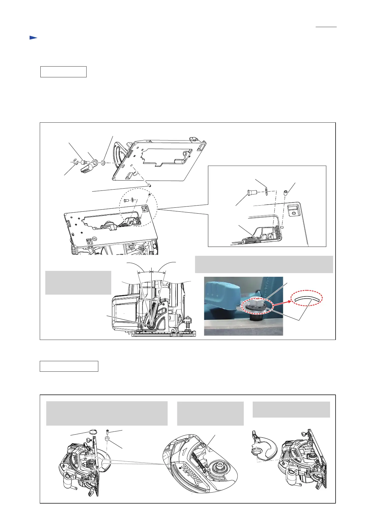
(1) Assemble the removed component parts to the new Base by reversing the disassembly procedure.
(Refer to Figs. 6, 5 and 3.)
Note in Assembling:
Do not forget to assemble Flat washers 6 and 7, and assemble Lever 45 to Angular guide section as drawn in Fig. 7.
Fig. 7
Fig. 8
Lever 45
Flat washer 6
M5x8 Hex socket
head set screw
M5x8 Hex socket
head set screw
Flat washer 7
6-7 Shoulder pin
Depth guide
15° 15°
DISASSEMBLING
1.Remove Retaining ring S-34 with 1R003.
Then, remove Rubber sleeve 6 and M6x20
Pan head screw.
2. Release the linkage of
Tension spring 4 from
Safety cover.
3. Remove Safety cover from
the machine.
Tension spring 4
(1) First, disassemble Safety cover for easy disassembling of Depth guide section. (See Fig. 8.)
Rubber sleeve 6
Retaining
ring S-34
M6x20 Pan
head screw
M6x20 Hex bolt
E-8 Bow stop ring
Fix the adjusted Lever 45
with E-8 Bow stop ring
as shown to right.
Lever 45
E-8 Bow stop ring
Be sure to mount E-8 Bow stop ring as shown below
for securely engaging Lever 45 with M6x20 Hex bolt.
M6 x20 Hex bolt
[3] DISASSEMBLY/ASSEMBLY
[3] -1. Base (cont.)

 Loading...