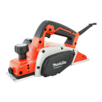
6 ENGLISH
1
2
3
4
5
6
7
8
9
Fig.6
►1.Insideankofgaugeplate2. Blade edge
3. Planer blade 4.Adjustingplate5. Screws
6. Heel 7. Back side of gauge base 8. Gauge plate
9. Gauge base
4. Placetheadjustingplateontheplanerblade.
Presstheadjustingplatesothatitsheelisushwith
the back side of gauge base. Tighten two screws on the
adjustingplate.
5. Sliptheheeloftheadjustingplateintothedrum
groove,thentthedrumcoveronit.
6. Tighten all the installation bolts evenly and alter-
nately with the socket wrench.
7. Repeat the procedure above for the other blade.
For tool with mini planer blades
To replace the mini planer blades, do the following
procedure.
1. Carefully clean the drum surfaces and the drum
cover.
2. Unscrew the three installation bolts with the socket
wrench.Removethedrumcover,adjustingplate,set
plate and the mini planer blade.
1
2
Fig.7
►1. Socket wrench 2. Bolts
3. Use the blade gauge to set the planer blades
correctly. Put the mini planer blade on the gauge base.
Applythecuttingedgeofthebladeontheinsideankof
the gauge plate.
1
2
3
4
5
6
7
8
9
10
Fig.8
►1. Screws 2.Adjustingplate3. Planer blade locating
lugs 4. Gauge plate 5.Heelofadjustingplate6. Set
plate 7.Insideankofgaugeplate8. Gauge base
9. Back side of gauge base 10. Mini planer blade
4. Looselyattachtheadjustingplatetothesetplate
withthescrews.Puttheadjustingplateandsetplate
on the gauge base. Fit the planer blade locating lugs on
the set plate into the mini planer blade groove.
5. Applytheheeloftheadjustingplateontotheback
side of the gauge base and tighten the screws. Check
the alignments carefully to ensure uniform cutting.
6. Sliptheheeloftheadjustingplateintothegroove
of the drum.
7. Putthedrumcoveronthesetplateandlooselyt
them onto the drum with the three bolts. Slip the mini
planer blade into the space between the drum and set
plate. Make sure that the planer blade locating lugs on
thesetplatetintheminiplanerbladegroove.
1
2
3
4
5
6
7
Fig.9
►1. Mini planer blade 2. Groove 3. Set plate 4. Bolts
5. Drum cover 6. Drum 7.Adjustingplate
8. Adjusttheminiplanerbladepositionlengthwayso
that the blade ends are clear and equidistant from the
housing on one side and the metal bracket on the other.
9. Tighten the three bolts with the socket wrench
provided and rotate the drum to check the clearances
between the blade ends and the tool body.
10. Checkthethreeboltsfornaltightness.
11. Repeat the procedure above for the other blade.

 Loading...