09.A 13-05-03
A520
}
B051
B540
B670
B550
B530 (n°4)
A490 (n°2)
A500
B020
B560
B030
B006
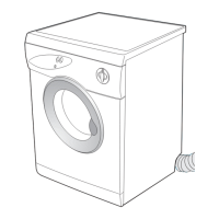
Step 14 Removing and/or replacing heater element (B560) and air inspection cover (B051):
(a) From the back of the drier, use a crosshead screwdriver to remove the four fixing screws (B530)
securing the heater element mounting cover (B550).
(b) Remove the two fixing screws (A490) securing the heater element (B560).
(c) Remove the fixing screw (A520) securing the air intake cover assembly (B051).
(d) Disconnect the heater element terminal block at the bottom of the drier, then remove the heater
element (B560).
To replace the heater element:
Disconnect the contacts of the thermostats (B006)(B030), noting their positions and recover:
- the maximum temperature thermostat (B006)
- the manual reset safety thermostat (B030)
- the thermostat plate (B020)
- the 2 thermostat plate fixing screws (A500)
(e) To re-assemble, follow the same procedure in reverse order.
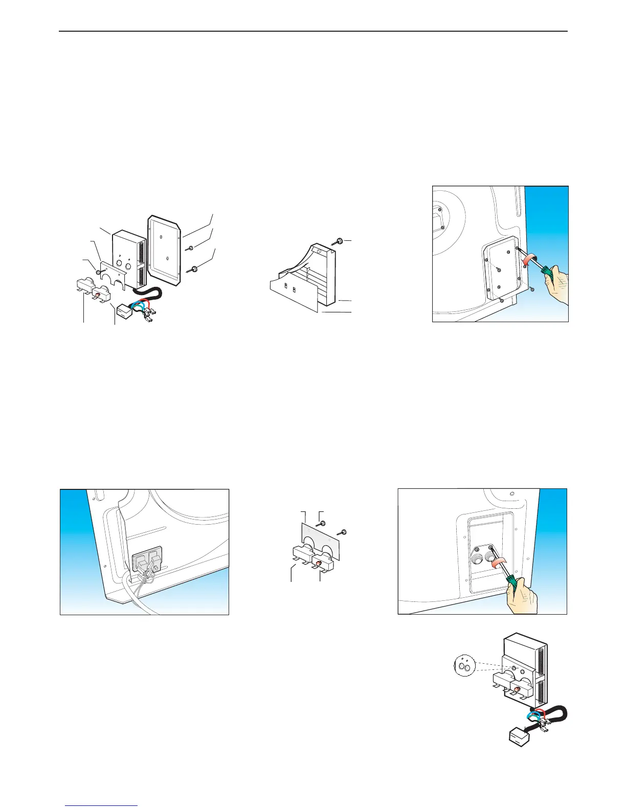
Step 15B
For driers produced from week 18 of 2003
(from serial number 200318...)
Technical Information code 466000021
Removing and/or replacing:
- the manual reset safety thermostat (B006)
- the automatic reset maximum temperature thermostat (B030)
(a) Remove the heater element mounting cover (B550) (Step 14)
(b) In order to have better access to the heater element terminal block, it is advisable
to remove the air intake inspection cover (B051) (Step 14) and disconnect it.
(c) Remove the 2 screws (A500) anchoring the thermostat mounting plate (B020)
and replace.
(d) To re-assemble, follow the same procedure in reverse order.
Step 15A
For driers produced prior to week 18 of 2003
Removing and/or replacing:
- the manual reset safety thermostat (B006)
- the automatic reset maximum temperature thermostat (B030)
(a) Remove the top cover (B360) as described in Step 1.
(b) To improve access, it is advisable to remove the rear panel (B580) following Step 16, dismantling
only those parts necessary.
(c) Remove the cover (B550) together with the heater element (B560) following Step 14, making sure
that the electric wiring is disconnected.
(d) Remove the two fixing screws (A500) securing the galvanised plate (B020), then remove the
thermostat to be replaced.
(e) To re-assemble, follow the same procedure in reverse order.
MAINTENANCE PROCEDURES
B020 A500
B030
B006
 Loading...