MAN B&W 5.12
Page 1 of 3
MAN Diesel
MAN B&W S65ME-C/-GI 198 87 99-4.0
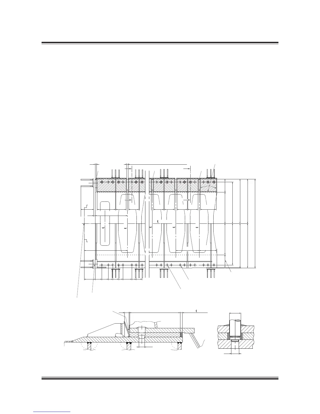
Epoxy Chocks Arrangement
For details of chocks and bolts see special drawings.
For securing of supporting chocks see special
drawing.
This drawing may, subject to the written consent of
the actual engine builder concerned, be used as a
basis for markingoff and drilling the holes for hold-
ing down bolts in the top plates, provided that:
1) The engine builder drills the holes for holding
down bolts in the bedplate while observing the
toleranced locations indicated on MAN B&W
Diesel & Turbos drawings for machining the
bedplate
2) The shipyard drills the holes for holding down
bolts in the top plates while observing the toler-
anced locations given on the present drawing
3) The holding down bolts are made in accord-
ance with MAN B&W Diesel & Turbos drawings
of these bolts.
#
25 mm thick dammings
2x1 off ø78 holes
M85x6 holes, predrilled ø79, in the
bedplate and ø64 holes in the topplate
ø79 holes in the bedplate and
ø64 holes in the topplate
'PFǤCPIGQHthrust shaft
65 mm free spaces for supporting wedges
1,084
812
0
310±1
612±1
812±1
1,088±1
1,288±1
1,696±1
1,896±1
2,172±1
1,920±1
2,052
2,062
4,124
1,920±1
2,052
2,062
730472472472472472472848
149265
600
65
508
2,000
615 1,447 1,447 615
ø64
ø79
251050
Effective 560
Epoxy wedges to
be chiselled after
curing to enable
mounting of side
chock liners
The width of
machining on
the underside
of bedplate
1,467 to
engine
A-A
B-B
B
B
A
A
##
thrust
bearing
cyl.1
cyl.2
cyl.3
Engine
aft cyl.
M85x6
ø64
Fig. 5.12.01: Arrangement of epoxy chocks and holding down bolts
078 88 96-7.0.0
 Loading...