MAN B&W 7.04
Page 3 of 3
MAN Diesel
198 67 68-4.2MAN B&W 98-60MC/MCC/ME/ME-C/ME-B/-GI, S50MC
Engine Selection Guides
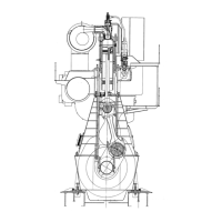
Fuel Oil Pipe Heat Tracing
178 50 625.0
Fig. 7.04.03: Fuel oil pipe heat tracing
The letters refer to list of ‘Counterflanges’
!&
!$
"$
"8
"&
&
8
&UELæPUMP
3HOCKæABSORBER
&UELæVALVE
$RAINæCYLæFRAME
3EEæDRAWING
&UELæOILæPIPESæINSULATION
,
&RESHæCOOLING
WATERæOUTLET
#YLæ
The steam tracing of the fuel oil pipes is intended
to operate in two situations:
1. When the circulation pump is running, there
will be a temperature loss in the piping, see
Fig. 7.04.02. This loss is very small, therefore
tracing in this situation is only necessary with
very long fuel supply lines.
2. When the circulation pump is stopped with
heavy fuel oil in the piping and the pipes have
cooled down to engine room temperature, as
it is not possible to pump the heavy fuel oil.
In this situation the fuel oil must be heated to
pumping temperature of about 50 ºC.
To heat the pipe to pumping level we recom-
mend to use 100 watt leaking/meter pipe.
176 94 23-4.4.0
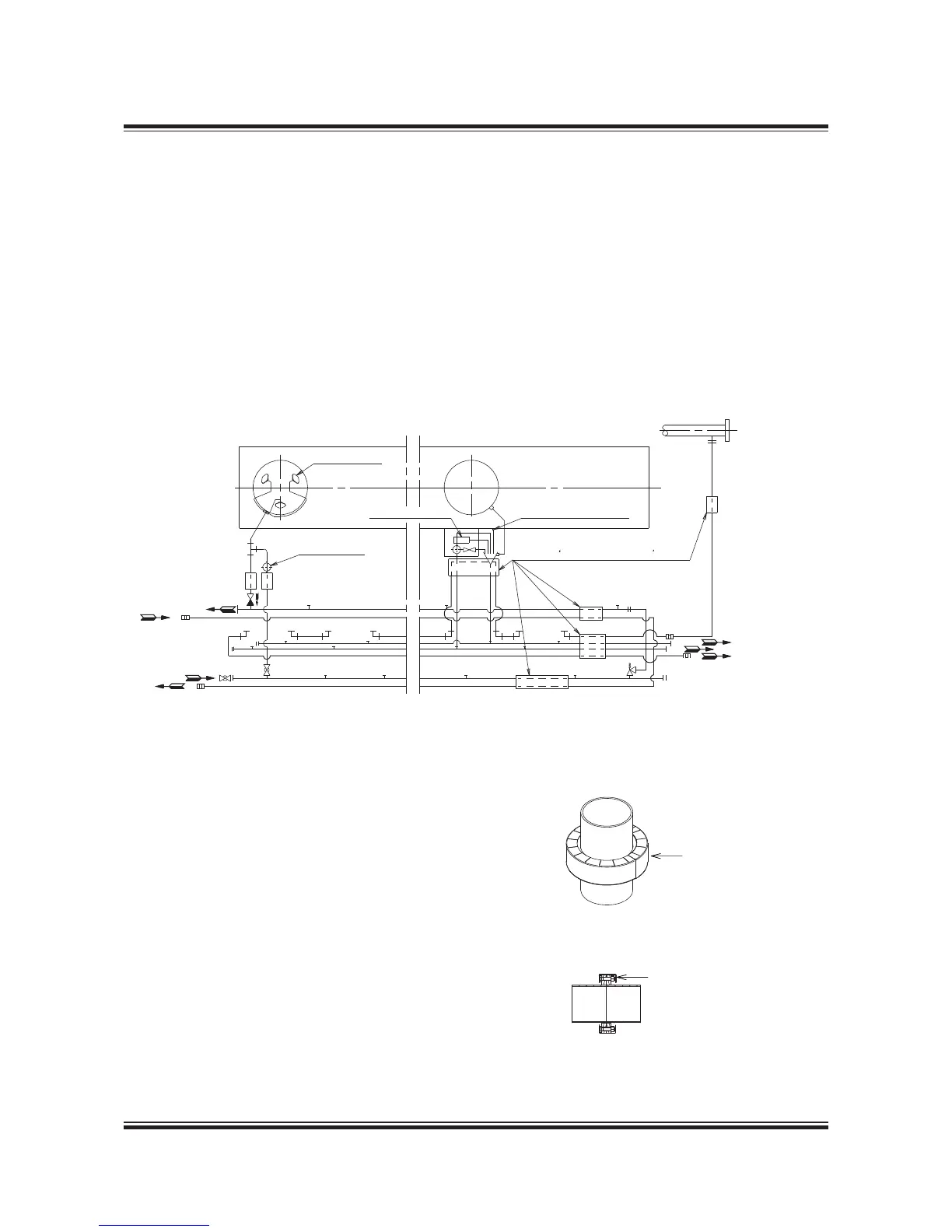
Fig. 7.04.04b: Spray Shields by clamping bands
To fulfill IMO regulations, fuel and oil pipes assem-
blies are to be secured by spray shields as shown.
To ensure tightness the spray shields are to be
applied after pressure test of the pipe system. as
shown in Fig. 7.04.04a and b.
To avoid leaks, the spray shields are to be in-
stalled after pressure testing of the pipe system.
Fig. 7.04.04a: Spray Shields by anti-splashing tape
Fuel Oil and Lubricating Oil Pipe Spray Shields
Plate 0,5 mm. thickness
Metal flange cover
 Loading...