MAN B&W 1.06
Page 1 of 7
MAN Diesel
198 89 14-5.2MAN B&W 90-50ME-C8-GI TII .2 and higher
Please note that engines built by our licensees are
in accordance with MAN Diesel & Turbo drawings
and standards but, in certain cases, some local
standards may be applied; however, all spare parts
are interchangeable with MAN Diesel & Turbo de-
signed parts.
Some components may differ from MAN Diesel &
Turbo’s design because of local production facili-
ties or the application of local standard compo-
nents.
In the following, reference is made to the item
numbers specified in the ‘Extent of Delivery’ (EoD)
forms, both for the ‘Basic’ delivery extent and for
some ‘Options’.
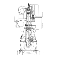
Bedplate and Main Bearing
The bedplate is made with the thrust bearing in
the aft end of the engine. The bedplate consists
of high, welded, longitudinal girders and welded
cross girders with cast steel bearing supports.
For fitting to the engine seating in the ship, long,
elastic holdingdown bolts, and hydraulic tighten-
ing tools are used.
The bedplate is made without taper for engines
mounted on epoxy chocks.
The oil pan, which is made of steel plate and is
welded to the bedplate, collects the return oil from
the forced lubricating and cooling oil system. The
oil outlets from the oil pan are vertical as standard
and provided with gratings.
The main bearings consist of thin walled steel
shells lined with bearing metal. The main bearing
bottom shell can be rotated out and in by means
of special tools in combination with hydraulic tools
for lifting the crankshaft. The shells are kept in po-
sition by a bearing cap.
Frame Box
The frame box is of welded design. On the ex-
haust side, it is provided with relief valves for each
cylinder while, on the manoeuvring side, it is pro-
vided with a large hinged door for each cylinder.
The crosshead guides are welded on to the frame
box.
The frame box is bolted to the bedplate. The bed-
plate, frame box and cylinder frame are tightened
together by stay bolts.
Cylinder Frame and Stuffing Box
The cylinder frame is cast and provided with ac-
cess covers for cleaning the scavenge air space,
if required, and for inspection of scavenge ports
and piston rings from the manoeuvring side. To-
gether with the cylinder liner it forms the scavenge
air space.
The cylinder frame is fitted with pipes for the pis-
ton cooling oil inlet. The scavenge air receiver, tur-
bocharger, air cooler box and gallery brackets are
located on the cylinder frame. At the bottom of the
cylinder frame there is a piston rod stuffing box,
provided with sealing rings for scavenge air, and
with oil scraper rings which prevent crankcase oil
from coming up into the scavenge air space.
Drains from the scavenge air space and the piston
rod stuffing box are located at the bottom of the
cylinder frame.
Cylinder Liner
The cylinder liner is made of alloyed cast iron and
is suspended in the cylinder frame. The top of the
cylinder liner is fitted with a cooling jacket. The
cylinder liner has scavenge ports and drilled holes
for cylinder lubrication.
Cylinder liners prepared for installation of temper-
ature sensors is basic execution on engines type
90 while an option on all other engines.
ME-GI Engine Description
 Loading...