MAN B&W 1.06
Page 5 of 7
MAN Diesel
198 89 14-5.2MAN B&W 90-50ME-C8-GI TII .2 and higher
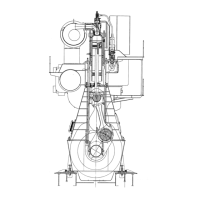
Hydraulic Cylinder Unit
The hydraulic cylinder unit (HCU), one per cylin-
der, consists of a base plate on which a distributor
block is mounted. The distributor block is fitted
with a number of accumulators to ensure that the
necessary hydraulic oil peak flow is available for
the electronically controlled fuel injection.
The distributor block serves as a mechanical
support for the hydraulically activated fuel oil
pressure booster and the hydraulically activated
exhaust valve actuator.
Fuel Oil Pressure Booster and
Fuel Oil High Pressure Pipes
The engine is provided with one hydraulically acti-
vated fuel oil pressure booster for each cylinder.
Injection of fuel oil (pilot oil) is activated by a multi-
way valve (FIVA) while injection of fuel gas is acti-
vated by the ELGI valve. Both valves are electroni-
cally controlled by the Cylinder Control Unit (CCU)
of the Engine Control System.
The fuel oil highpressure pipes are of the double-
wall type with built-in conical support. The pipes
are insulated but not heated.
Further information is given in Section 7.00.
Gas Pipes
A chain pipe system is fitted for high-pressure
gas distribution to each adapter block. The chain
pipes are connected to the gas control block via
the adapter block.
Gas pipes are designed with double walls, with
the outer shielding pipe designed so as to prevent
gas outflow to the machinery spaces in the event
of leaking or rupture of the inner gas pipe.
The intervening gas pipe space, including also the
space around valves, flanges, etc., is vented by
separate mechanical ventilation with a capacity of
30 air changes per hour. Any leakage gas will be
led to the ventilated part of the double-wall piping
system and will be detected by HC sensors.
The pressure in the intervening space is kept be-
low that of the engine room. The extractor fan mo-
tor is placed outside the duct and the machinery
space. The ventilation inlet air must be taken from
a gas safe area and exhausted to a safe place.
The gas pipes on the engine are designed for and
pressure tested at 50% higher pressure than the
normal working pressure, and are supported so
as to avoid mechanical vibrations. The gas pipes
should furthermore be protected against drops of
heavy items.
The chain piping to the individual cylinders are
flexible enough to cope with the mechanical stress
from the thermal expansion of the engine from
cold to hot condition. The chain pipes are connect-
ed to the gas control blocks by means of adapter
blocks.
The gas pipe system is designed so as to avoid
excessive gas pressure fluctuations during opera-
tion.
The gas pipes are to be connected to an inert gas
purging system.
Gas Control Block
The gas control block consists of a square steel
block, bolted to the HCU side of the cylinder
cover.
The gas control block incorporates a large volume
accumulator and is provided with a window/shut-
down valve, a purge valve and a blow-off valve. All
high-pressure gas sealings lead into spaces that
are connected to the double-wall pipe system, for
leakage detection.
Minute volumes around the gas injection valves in
the cylinder cover are kept under vacuum from the
venting air in the double-wall gas pipes.
Internal bores connect the hydraulic oil, sealing
oil and the gas to the various valves. A non-return
valve is positioned at the gas inlet to the gas ac-
cumulator, in order to ensure that gas cannot flow
backwards in the system.
 Loading...