MAN B&W 13.01
Page 1 of 1
MAN Diesel
MAN B&W 65-60MEGI 198 89 70-6.2
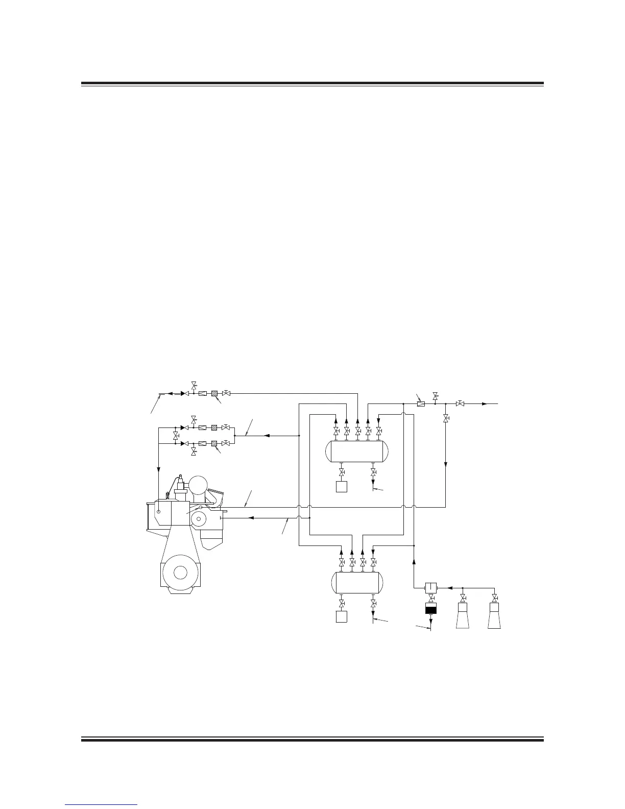
Fig. 13.01.01: Starting and control air systems
The starting air of 30 bar is supplied by the start-
ing air compressors to the starting air receivers
and from these to the main engine inlet ‘A’.
Through a reduction station, filtered compressed
air at 7 bar is supplied to the control air for ex-
haust valve air springs, through engine inlet ‘B’
Through a reduction valve, compressed air is sup-
plied at 10 bar to ‘AP’ for turbocharger cleaning
(soft blast), and a minor volume used for the fuel
valve testing unit.
Through a reduction valve, compressed air is sup-
plied at 1.5 bar to the leakage detection and venti-
lation system for the double-wall gas piping.
Please note that the air consumption for control
air, safety air, turbocharger cleaning, sealing air for
exhaust valve, for fuel valve testing unit and vent-
ing of gas pipes are momentary requirements of
the consumers.
The components of the starting and control air
systems are further desribed in Section 13.02.
For information about a common starting air sys-
tem for main engines and MAN Diesel & Turbo
auxiliary engines, please refer to our publication:
Uni-concept Auxiliary Systems for Two-Stroke Main
Engines and Four-Stroke Auxiliary Engines
The publication is available at www.marine.man.eu
→ ’Two-Stroke’ → ’Technical Papers’.
556 74 77-6.2.0
Oil & water
separator
To bilge
Reduction station
Pipe, DN25 mm
Pipe a, DN *)
Starting air
receiver 30 bar
Starting air
receiver 30 bar
Filter,
40 μm
To
bilge
Main
engine
Air compressors
To fuel valve
testing unit
BAP
A
Reduction valve
PI
PI
Pipe, DN25 mm
Filter,
40 μm
To gas piping double-wall
venting air intake
Heat tracing by
jacket water or
steam
The letters refer to list of ‘Counterflanges’
*) Pipe a nominal dimension: DN125 mm
Starting and Control Air Systems
 Loading...