MAN B&W 15.06
Page 2 of 2
MAN Diesel
198 49 11-1.4MAN B&W S65ME-C8/-GI
078 38 48-6.2.2
M1 M3
F3
F3F2
F1
MAN
M1
F2
F1
Mitsubishi
M3
ABB A-L
M1
F1
F2
M3
F3
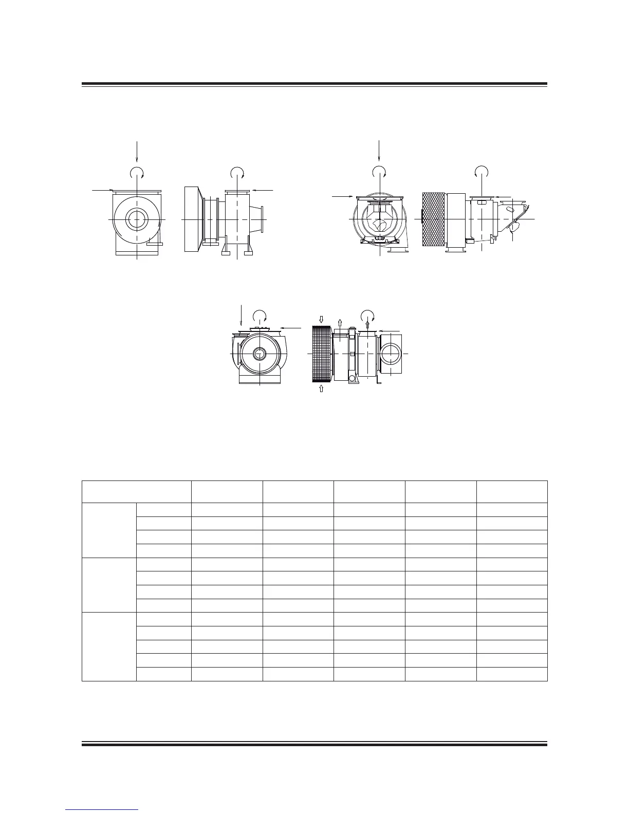
Fig. 15.06.03: Forces and moments on the turbochargers’ exhaust gas outlet flange
Table 15.06.04: The max. permissible forces and moments on the turbocharger’s gas outlet flanges
Turbocharger M1 M3 F1 F2 F3
Make Type Nm Nm N N N
MAN
TCA55 3,400 6,900 9,100 9,100 4,500
TCA66 3,700 7,500 9,900 9,900 4,900
TCA77 4,100 8,200 10,900 10,900 5,400
TCA88 4,500 9,100 12,000 12,000 5,900
ABB
A275 3,300 3,300 5,400 3,500 3,500
A180 / A280 4,600 4,600 6,800 4,400 4,400
A185 / A285 6,600 6,600 8,500 5,500 5,500
A190 8,700 8,700 10,300 6,700 6,700
MHI
MET53 4,900 2,500 7,300 2,600 2,300
MET60 6,000 3,000 8,300 2,900 3,000
MET66 6,800 3,400 9,300 3,200 3,000
MET71 7,000 3,500 9,600 3,300 3,100
MET83 9,800 4,900 11,700 4,100 3,700
Data for more turbocharger makes and types for the S65ME-C8/-GI engines are available on request.
Table 15.06.04 indicates the maximum permissible forces (F1, F2 and F3) and moments (M1 and M3), on
the exhaust gas outlet flange of the turbo-charger(s). Reference is made to Fig. 15.06.03.
 Loading...