MAN B&W 15.07
Page 1 of 1
MAN Diesel
198 49 14-7.3MAN B&W S65ME-C8/-GI
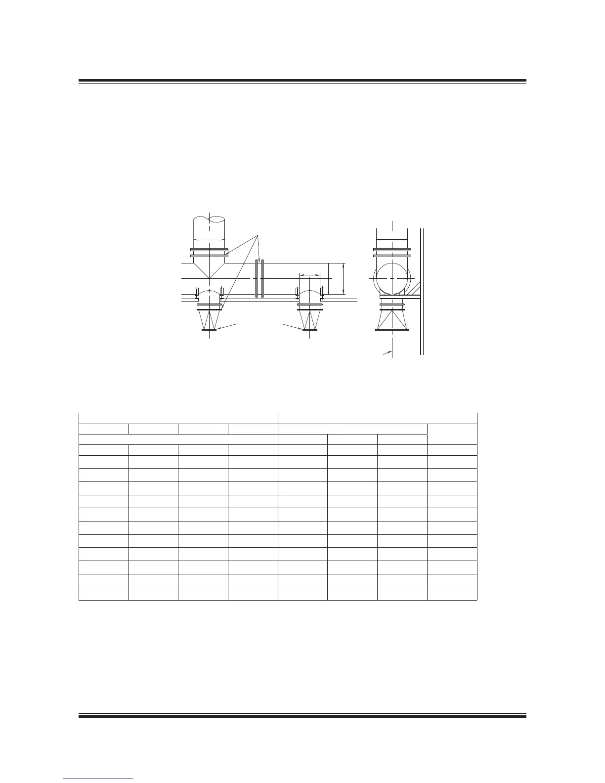
%XPANSIONæJOINT
OPTIONæææ
4RANSITIONæPIECE
OPTIONæææ
#ENTREæLINEæTURBOCHARGER
$
$
$
$
Diameter of Exhaust Gas Pipes
178 09 395.2
Fig. 15.07.01: Exhaust pipe system, with turbocharger located on exhaust side of engine
Gas velocity Exhaust gas pipe diameters
35 m/s 40 m/s 45 m/s 50 m/s D0 D4
Gas mass flow 1 T/C 2 T/C 3 T/C
kg/s kg/s kg/s kg/s [DN] [DN] [DN] [DN]
20.5 23.4 26.3 29.2 1,050 750 600 1,050
22.4 25.7 28.9 32.1 1,100 800 650 1,100
24.5 28.0 31.5 35.1 1,150 800 650 1,150
26.7 30.5 34.3 38.2 1,200 850 700 1,200
31.4 35.8 40.3 44.8 1,300 900 750 1,300
36.4 41.6 46.8 51.9 1,400 1,000 800 1,400
41.7 47.7 53.7 59.6 1,500 1,050 850 1,500
47.5 54.3 61.1 67.8 1,600 1,150 900 1,600
53.6 61.3 68.9 76.6 1,700 1,200 1,000 1,700
60.1 68.7 77.3 85.9 1,800 1,300 1,050 1,800
67.0 76.5 86.1 95.7 N.A. 1,300 1,100 1,900
Table 15.07.02: Exhaust gas pipe diameters and exhaust gas mass flow at various velocities
The exhaust gas pipe diameters listed in Table
15.07.02 are based on the exhaust gas flow ca-
pacity according to ISO ambient conditions and
an exhaust gas temperature of 250 ºC.
The exhaust gas velocities and mass flow listed
apply to collector pipe D4. The table also lists the
diameters of the corresponding exhaust gas pipes
D0 for various numbers of turbochargers installed.
 Loading...