MAN B&W 16.01
Page 5 of 10
MAN Diesel
MAN B&W ME/MEC/-GI engines 198 79 23-5.2
Actuators
Sensors
Actuators
Sensors
On Bridge
In Engine Control Room
On Engine
ECU A
EICU A EICU B
ECU B
Backup Operation Panel
MOP B
Bridge Panel
Local Operation
Panel LOP
Auxiliary
Blower 1
Auxiliary
Blower 2
ECR Panel
ACU 1
CCU
Cylinder 1
CCU
Cylinder n
ACU 3ACU 2
SAV
Cylinder n
Main Operation Panel
MOP A
Fuel
booster
position
Cylinder 1
Exhaust
valve
position
Cylinder 1
Exhaust
valve
position
Cylinder n
Fuel
booster
position
Cylinder n
FIVA
Valve
Cylinder n
AL
Cylinder 1
SAV
Cylinder 1
AL
Cylinder n
Angle Encoders
Marker Sensor
FIVA
Valve
Cylinder 1
M
M
Pump 1
M
M
M
M
M
Auxiliary
Blower 3
Auxiliary
Blower 4
ME ECS Common Control Cabinet
in Engine Control Room/Engine Room
Pump 2
Pump 1
Pump 2
Pump 3
Pump 4
Pump 5
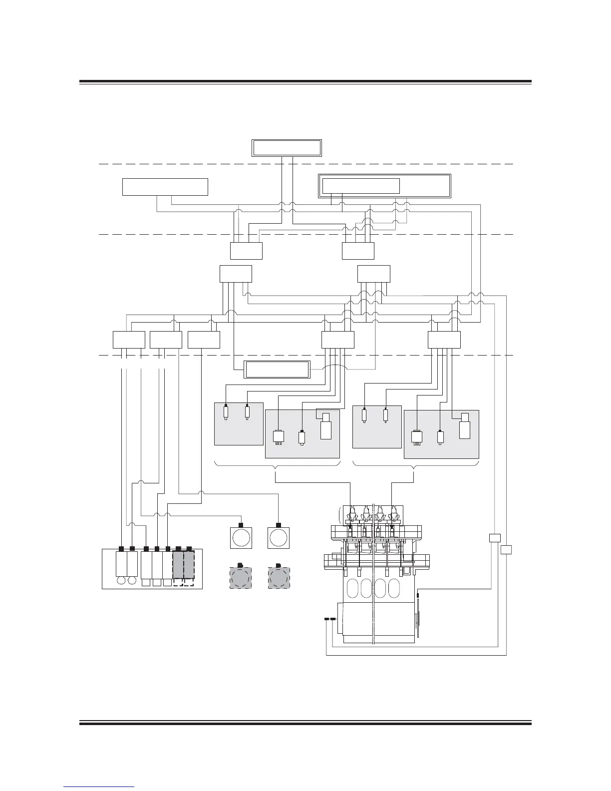
Engine Control System Layout with Common Control Cabinet
178 61 76-9.1
Fig. 16.01.01b: Engine Control System layout with ECS Common Control Cabinet for mounting in
ECR or on engine, option: 4 65 602
 Loading...