MAN B&W 16.01
Page 10 of 10
MAN Diesel
MAN B&W ME/MEC/-GI engines 198 79 260.1
Option:
4 50 166
4 50 665
Reduction
unit
30 > 7 bar
Control
air
supply
7 bar
Starting
air
supply
30 bar
Service/blocked
Main starting
valve
Slow turning
valve
Starting
valves
Turning gear
Exhaust valve
Control
air
supply
7 bar
Connected to
oil filter
Connected to
oil mist detector
LOP
Option:
Connection to
exhaust gas
bypass system
Option:
4 60 110
Connection to
turbocharger
cutout system
Safety relief
valve
Fuel cutoff
Shut down
Only if GL
Open
Open
F
X
ZV 8020 Z
PT 8505 AL YL
PT 8503A I C AL AH
PT 8503B I C AL AH
PI 8503
ZS 1109A+B I C
ZS 1110A+B I C
ZS 1116A+B C
ZS 1117A+B C
ZV 1120N C
ZV 1121A C
ZV 1121B C
ZV 1114 C
ZS 1111A+B I C
ZS 1112A+B I C
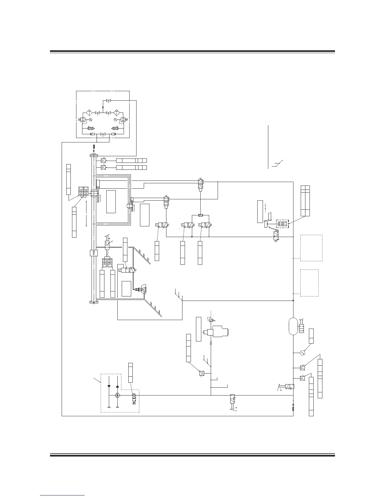
The drawing shows the system
in the following conditions:
Stop position
Pneumatic pressure on
Electric power on
Main starting valve in
Service position
Symbol Description
One per cylinder
PT 8501A I A C
PT 8501B I A C
Pneumatic Manoeuvring Diagram
507 96 333.7.0
Fig. 16.01.03: Pneumatic Manoeuvring Diagram
The letters refer to list of ‘Counterflanges’
The item no. refer to ‘Guidance Values Automation’
 Loading...