J
L
M
K
N
Q
O
S
O
M
R
P
O
H
C
B
I
H
B
I
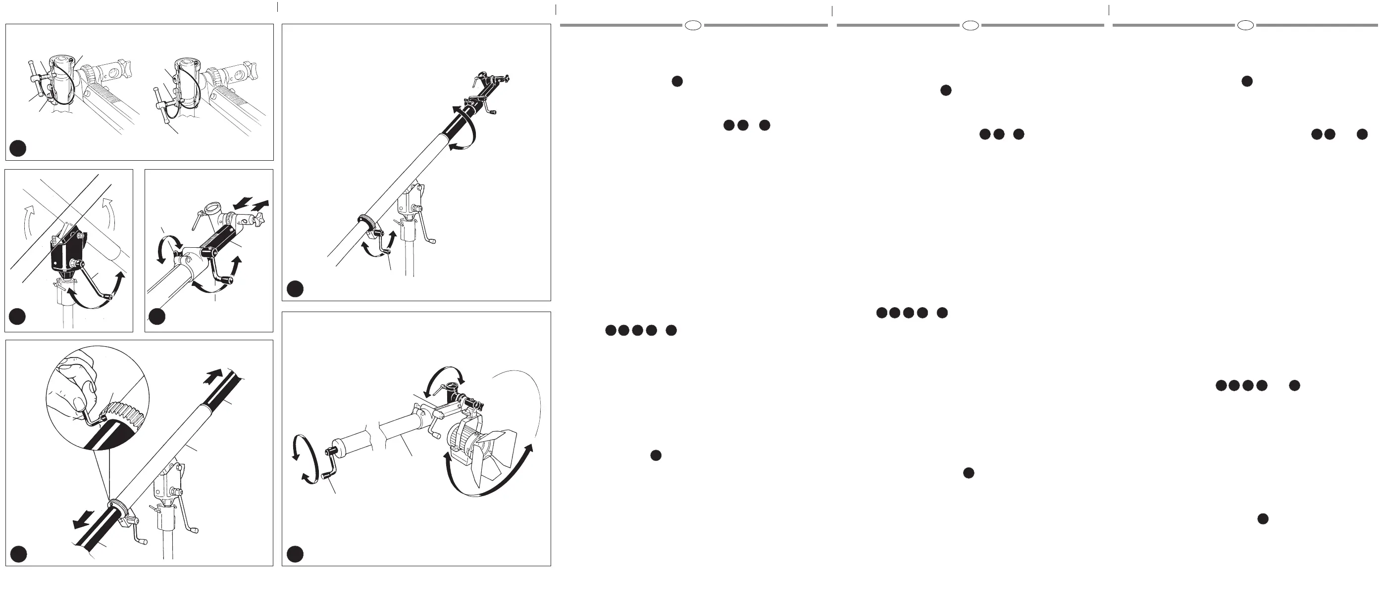
The Mega Boom is designed to support and remotely position luminaires (or
other equipment) of up to a maximum load of 6 Kg (13 +lbs) at maximum
extension using the well positioned crank handles for all movements.
MOUNTING THE MEGA BOOM
Mount the Boom on a suitable stand (example Art. 087NW or 087NWB - USA
3075) by inserting the 28 mm (1 1/8”) stud “A” (fig. 1) into the top of the stand
and then tighten the locking knob.
ATTACHING THE LUMINAIRE TO THE BOOM &
There are two sockets into which the luminaire can fit - 28 mm (1 1/8”) or
17,5 mm (5/8”).
For luminaires with a 28 mm (1 1/8”) spigot, refer to fig. 2
– Loosen locking tommy bar “B”
– Insert the luminaire spigot as illustrated (fig. I) into the boom socket with the
larger diameter of the boom socket upper most.
– Insert safety pin “D” into the hole in the luminaire spigot (fig. II) when it
protrudes through the boom socket.
– Allow the luminaire to fall back on the safety pin which must be recessed into
the top of the boom socket (fig. III).
– Lock the tommy bar “B” tightly by rotating clockwise.
Note: The 28 mm boom socket has two positions for the tommy bar lock off to
enable you to adjust dependant on the type of 28 mm luminaire spigot and the
position of the grooved recess on the spigot (fig. 4) into which the locking
tommy bar screw must fit for safety.
For luminaires with a 17,5 mm (5/8”) spigot, refer to fig. 3
– Loosen knob “F” by turning anticlockwise
– Insert the luminaire spigot into the boom socket “G”
– Lock the knob “F” by turning clockwise.
CONTROLS &
Fig. 5 Crank handle “J” controls the tilt of the Boom Arm from the horizontal:
+ 30° to – 40°
Fig. 6 Crank handle “K” controls the geared extension “M” and knob “L” lock
the extension in place.
Fig. 7 The centre of gravity or extension “O” can be further adjusted by
unlocking Allen Screw “N” and sliding “O” forward or backwards within
“P”. When the ideal position is achleved, lock the Allen Screw “N” with a
4 mm Allen key.
Fig. 8 The luminaire can be rotated 360° around the Boom Arm by crank handle
“R”.
Fig. 9 The crank handle “S” at the end of the Boom Arm controls the forward
rotation up to 360°.
BALANCING THE BOOM
Good balance reduces the swaying motion of the luminaire when the boom is
being operated.
The Mega Boom is supplied with a counter balance sandbag.
Fill the bag (Max 30 kg to 35 kg - 66 lbs to 75 lbs) with sand and hang it over
the Boom Arm (fig. 1). Additional weights can be attached to loops on the
sandbag “T”.
La Mega Boom è stata realizzata per sostenere corpi illumninanti (peso
massimo caricabile 6 Kg alla massima estensione) o altre attrezzature il cui
orientamento è comandabile agevolmente a distanza.
I comandi sono realizzati tramite pratiche e comode manovelle a cremagliera.
FISSAGGIO DELLA GIRAFFA
Fissare il codolo di attacco “A” della giraffa allo stativo più idoneo (ad esempio
Art. 087NW o 087NWB - USA 3075) (fig. 1). Il diametro del codolo “A” è di 28
mm (1 1/8”).
FISSAGGIO DEL CORPO ILLUMINANTE E
Se il corpo illuminante dispone di codolo da 28 mm (1 1/8”), vedere fig. 2:
– allentare la leva a vite “B” (fig. I) e inserire il codolo del corpo illuminante dalla
parte di Ø inferiore dell’attacco “C”
– inserire la spina di sicurezza “D” nel foro del codolo sul lato opposto
dell’attacco (fig. II) curando che vada ad alloggiarsi nella sede “E” (fig. III)
– serrare fortemente la leva “B” ruotandola in senso orario (fig. III)
A questo punto il corpo illuminante è bloccato: verificare che la spina di
sicurezza “D” non fuoriesca dalla sede “E”.
N.B.: L’attacco “C” per codoli da 28 mm (1 1/8”) è provvisto di doppio foro
filettato (fig. 4) per la leva a vite “B”.
A seconda di dove è posizionato lo scarico del codolo del corpo illuminante
fissare la vite “B” nel foro “H” o “I” .
Se il corpo illuminante dispone di codolo da 17,5 mm (5/8”), vedere fig. 3:
– allentare la manopola “F”
– inserire il codolo del corpo illuminante nell’attacco “G”
– serrare fortemente la manopola “F” ruotandola in senso orario
COMANDI E
Fig. 5 Con la manovella “J” si comanda l’inclinazione della giraffa rispetto al
piano orizzontale (da + 30° a – 40°).
Fig. 6 Con la manovella “K” si regola l’estensione della giraffa:
– allentare la manopola “L”
– estendere la prolunga “M” fino alla misura desiderata ruotando la
manovella “K”
– bloccare a fondo la manopola “L” ruotando in senso orario
Fig. 7 Allentando la vite “N” è possibile modificare la posizione del tubo “O”
rispetto al tubo “P” :
– utilizzando la chiave esagonale da 4 mm “Q” allentare la vite “N”
– far scorrere il tubo “O” fino alla misura desiderata
– serrare la vite “N”
Fig. 8 Con la manovella “R” si comanda la rotazione completa del corpo
illuminante attorno all’asse della giraffa.
Fig. 9 Con la manovella “S” si comanda la rotazione completa mostrata in
figura del corpo illuminante.
BILANCIAMENTO DELLA GIRAFFA
L’Art. 425B è provvisto di sacca di contrappeso: equilibrare il carico riempiendo
la sacca (capacità massima 30-35 kg ) e fissandola sulla giraffa (fig. 1).
In caso di necessità ancorare eventuali pesi supplementari agli occhielli “T”.
N.B.: Un buon bilanciamento riduce le oscillazioni del corpo illuminante durante
l’utilizzo.
Der Mega Boom wurde entwickelt, um Leuchten (oder anderes Zubehör) bis zu
einem Gewicht von 6 kg (bei vollem Auszug) mit Hilfe der Bedienungskurbeln
zu positionieren.
BEFESTIGUNG DES MEGA BOOMS
Befestigen Sie den Mega Boom auf einem geeigneten Stativ (zum Beispiel
Art. 087NW/087NWB - USA 3075) indem Sie den 28 mm Zapfen “A” (fig. 1) in
den Sockel am Ende des Stativs einsetzen und die Sicherungsschraube
anziehen.
BEFESTIGUNG DER LEUCHTE AUF DEM MEGA BOOM UND
Der Megaboom ist mit zwei Sockeln (zur Befestigung der Leuchte) ausgerüstet:
28 mm (1 1/8”) und 17,5 mm (5/8”).
Für Leuchten mit einem 28 mm (1 1/8”) Spigot beachten Sie bitte fig. 2 und die
nachfolgenden Instruktionen:
– Lösen Sie die Blockierschraube “B” im Gegenuhrzeigersinn.
– Führen Sie den Spigot wie in Abb. I gezeigt bis zum Anschlang in den Sockel
“C” ein. Achten Sie darauf, daß das Sockelende mit dem größeren
Durchmesser nach oben zeigt.
– Stecken Sie den Sicherungsstift “D” durch die Öffnung im Spigot (Abb. II).
– Wenn Sie die Leuchte nun vorsichtig heruntergleiten lassen, so muß der
Sicherungsstift in der erweiterten Öffnung des Sockels sicher aufliegen.
(Abb. III)
– Arretieren Sie nun die Blockierschraube “B” im Uhrzeigersinn, bis die
Leuchte sicher positioniert ist und sich nicht mehr im Sockel dreht.
Achtung: Der 28 mm Spigot ist mit zwei Einschraubgewinden für die
Blockierschraube “B” ausgerüstet. Wechseln Sie die Blockierschraube je nach
Spigot-Typ, damit immer gewährleistet ist, daß die Schraube in die Vertiefung
im Spigot eingedreht werden kann (fig. 4).
Für Leuchten mit einem 17,5 mm (5/8”) Spigot beachten Sie bitte fig. 3 und die
nachfolgenden Instruktionen:
– Lösen Sie die Blockierschraube “F” im Gegenuhrzeigersinn.
– Führen Sie den Leuchtenspigot bis zum Anschlag in den Sockel “G” ein.
– Arretieren Sie die Blockierschraube “F” im Uhrzeigersinn, bis die Leuchte
sicher positioniert ist.
BEDIENUNGSFUNKTIONEN UND
Fig. 5 Drehkurbel “J” zur Neigung des Mega Booms (+ 30° bis – 40°)
Fig. 6 Drehkurbel “K” zur Veränderung des Auszuges “M”. Blockierschraube
“L” Arretierung des Auszuges “M”.
Fig. 7 Die Balance des Hauptrohres “O” kann verstellt werden. Lösen Sie dazu
die Imbusschraube “N” mit einem 4 mm imbusschlüssel. Nun kann das
Rohr “O” in der Halterung “P” hin-und hergeschoben werden. Sobald
der Mega Boom optimal ausbalanciert ist, ziehen Sie die Imbusschraube
“N” wieder an.
Fig. 8 Mit der Drehkurbel “R” kann die Leuchte um 360° (in der Längsachse
des Mega Booms) gedreht werden.
Fig. 9 Mit der Drehkurbel “S” am Ende des Mega Booms kann die
Leuchtenneigung verändert werden. Diese Bewegung kann um 360°
ausgeführt werden.
AUSBALANCIEREN DES MEGA BOOMS
Eine gute Ausbalancierung erleichtert die Bedienung des Mega Booms. Der
mitgelieferte Gegengewichtssack kann mit bis zu 30 bis 35 kg Sand gefüllt
werden und muß über das Ende des Galgenausleger gehängt werden (fig. 1).
Zusätzliche Gegengewichte können an den Laschen des Sandsackes “T”
befestigt werden.
5 6
4
8
9
1
2 3 4
5 6 7 8 9
1
1
2 3 4
5 6 7 8 9
1
1
2 3 4
5 6 7 8 9
1
 Loading...