3-89
IT EN ES
648870 IT-EN-ES (04/05/2015)
H5 - Regolare i fari anteriori
Raccomandazioni per la regolazione
( Secondo le norme ECE-76/756 76/761
ECE20).
Regolazione del -2% del fascio degli anab-
baglianti rispetto all’asse orizzontale del
proiettore.
Procedura di regolazione
- Mettere il carrello elevatore, a vuoto
in posizione di trasporto, perpendicolar-
mente ad un muro bianco, su di un terre-
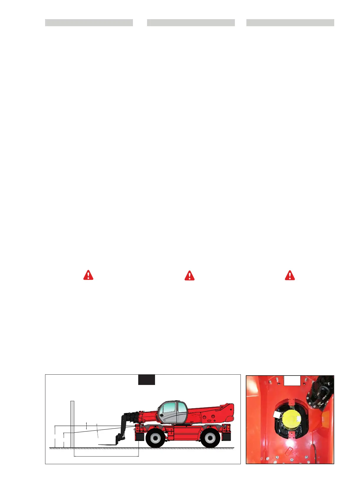
no piano e orizzontale (Fig. H5).
- Controllare la pressione dei pneumatici
(Vedi capitolo: B3 - CONTROLLARE
LA PRESSIONE DEI PNEUMATICI E IL
SERRAGGIO DEI BULLONI DELLE RUOTE
nella parte: 3 - MANUTENZIONE).
- Mettere la leva dell’invertitore di marcia
in folle e azionare il freno di stazionameto.
Calcolo dell’altezza degli anabbaglianti (h2)
FIG. H5
h1 = Altezza rispetto al suolo degli
anabbaglianti.
h2 = Altezza del fascio regolato.
I = Distanza tra gli anabbaglianti e il
muro bianco.
h2 = h1- (l x 2/100)
H6 - Far controllare e pulire gli anelli
trasmettitori del collettore elettrico
rotante (dopo 3 mesi di inattività)
Sollevare il braccio e collocare il cuneo di
sicurezza sullo stelo del martinetto di solle-
vamento (vedere: 1 - ISTRUZIONI E NORME DI
SICUREZZA: ISTRUZIONI DI MANUTENZIONE
DEL CARRELLO ELEVATORE).
RIVOLGERSI AL VOSTRO AGENTE O CON
CESSIONARIO.
h2
h1
I
+%
-%
-2%
H5
H5 - Adjust the front headlamps
Recommended setting
(As per standard ECE-76/756 76/761 ECE20)
Set to - 2% of the dipped beam in relation
to the horizontal line of the headlamp.
Adjusting procedure
- Place the lift truck unloaded and in the
transport position and perpendicular to a
white wall on flat, level ground (Fig. H5).
- Check the tyre pressures (See chapter:
B3 - CHECK THE TYRE PRESSURES AND
THE WHEEL NUTS TORQUE in paragraph:
3 - MAINTENANCE).
- Put the gear reverser lever in neutral and
action the parking brake.
Calculating the height of the dipped
beam (h2) FIG. H5
h1 =Height of the dipped beam in
relation to the ground.
h2 =Height of the adjusted beam.
l =Distance between the dipped
beam and the white wall.
h2 = h1- (l x 2/100)
H6 - Have the rotary electrical slip rings
checked and cleaned (after 3 mon-
ths of shutdown)
Raise the boom and place the boom safety
wedge on the rod of the lifting cylinder (see:
1 - OPERATING AND SAFETINSTRUCTIONS:
LIFT TRUCK MAINTENANCE INSTRUCTIONS).
CONTACT YOUR AGENT OR DEALER.
H6
H5 -Regular los faros delanteros
Consejos para la regulación (Según las nor-
mas ECE-76/756 76/761 ECE20)
Regulación del -2% del haz de las luces
bajas respecto al eje horizontal del foco
Procedimiento de regulación
- Poner la carretilla elevadora, en vacío
en posición de transporte, perpendicu
larmente a un muro blanco, sobre un
terreno plano y horizontal (Fig. H5).
- Controlar la presión de los neumáticos
(Ver capítulo: B – CONTROLAR LA
PRESION DE LOS NEUMÁTICOS Y
EL AJUSTE DE LOS PERNOS DE
LAS RUEDAS en la parte: 3 –
MANTENIMIENTO).
- Poner la palanca del inversor de
marcha en punto muerto y apretar el
freno de estacionamiento.
Cálculo de la altura de las luces bajas
(h2) FIG. H5
h1 = Altura respecto al suelo de
las luces bajas
h2 = Altura del haz de luz regulado.
I = Distancia entre las luces
bajas y el muro blanco.
h2 = h1- (l x 2/100)
H6 - Hacer controlar y limpiar los anil-
los de transmisión del colector
eléctrico rotativo (después de 3
meses de inactividad)
Elevar el brazo y colocar el calce de segu-
ridad en la barra del gato elevador (ver:
1 – INSTRUCCIONESY CONSIGNAS DE
SEGURIDAD DE LA CARRETILLA ELEVADORA).
CONTACTE SU AGENTE O
CONCESIONARIO.


 To Next Page
 Loading...