Installation Section 2
22
Part Number 000007924 5/14
30" Dual Evaporator Models
Step 7 Connect wiring to condensing unit and ice
machine head section
Attach wiring to terminal strip in condensing unit control
box and control board in ice machine head section.
Rewire transformer when supply voltage is 208V/60HZ/
1PH and match low voltage wire connections in ICVD
condensing unit to ice machine control board
connections (See page
16). Connections on an RDI
condensing unit are identical to the ICVD connections
Step 8 Leak Check The Refrigeration System
A. Connect power to the ice machine head section -
Do not connect power to the ICVD condensing
unit.
B. Press the power switch and energize the ice
machine for 60 seconds to equalize pressures.
C. Disconnect power to the ice machine head
section.
D. Leak check lineset connections, S trap and all
factory joints in head section and condensing
unit.
E. Connect power to the ICVD condensing unit and
allow system to pump down.
Step 9 Insulation Requirements
• To prevent condensation the entire suction line
including the shut-off valve must be insulated.
• All insulation must be airtight and sealed at both
ends.
The following insulation requirements prevent
condensation at 90°F (32.2°C) ambient 90% Relative
Humidity. If higher humidity is expected, increase
insulation thickness:
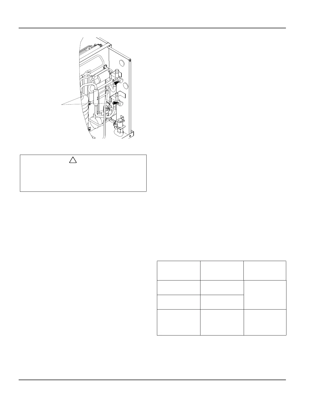
After opening suction, discharge and receiver
service valves, refrigerant pressure will not be
detected until the ice machine starts a freeze cycle
and the solenoid valves energize.
USE ALLEN WRENCH
TO OPEN (TURN
COUNTERCLOCKWISE)
LIQUID AND SUCTION
LINE SHUT OFF
VALVES
Suction Line Liquid Line
Min.
Insulation
Thickness
3/4 inch
(19.1 mm)
1/2 inch
(12.7 mm)
1/2" (13 mm)
Suction Line
1/4" (7 mm)
Liquid Line
5/8 inch
(15.9 mm)
3/8 inch
(9.5 mm)
3/4 inch
(19.1 mm)
5/8 inch
(15.9 mm)
3/4" (19 mm)
Suction Line
1/4" (7 mm)
Liquid Line