1.7.1
1.7.1.1
1.7.2
1.7.1.2
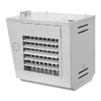
Equipment descriptions
Beschreibung der Komponenten
1.7
GSE
GSE-O
GSE
GSE-O
GSE
GSE-O
GSE
GSE-O
T Type
A Gas combination valve
B Burner control
I Natural gas
(1)
Only for NL, BE and DE.
Gas control
Gas control system for fully automatic control and
protection of gas-fired heating units with electronic
ignition
A Burnercontrol
B Warninglight/resetbutton
C Settingscrew gaspressure
D Electrical connection
E Gas pressure nipple (inlet side)
F Gas inlet/outlet
Second Safety shut-off valve
Safety shut-off valve 3/4” operating in combination
with the Honeywell (V4400) gas control set.
Positions
A Flamerod
B Ignition electrod
T Gerätegröße (Typ)
A Gasmagnetventil:
B Brennersteuergerät
I Geräte für Erdgas
(1)
Nur für NL, BE und DE.
Gasreglerkombination
Gasreglerkombination zum automatischen Regeln
und Überwachen von einem Warmlufterzeuger.
A Brennerautomat
B Störungslampe/Resettaste
C Einstellschraube Druckregler
D Elektroanschlüsse
E Meßnippel für Vordruck
F Gaseintritt b.z.w. Austritt
Zweite Sicherheits-Absperrvorrichtung
Dieses Sicherheitsventil arbeitet zusammen mit dem
Gasregelventil von Honeywell (V4400).
Siehe 1)
Einstellmaße
A Ionisationselektrode
B Zündelektrode
35
 Loading...