4 Remove outlet box cover by pulling downward while
simultaneously pushing in side of cover at indicated point to
release locking tab. Connect wire from wall switch to motor
leads and light receptacle wires using approved wire connector -
white to white, black to black. Models A664IC, MM664IC,
MM667IC, and MM667ICF Fan/Lights can be wired so that
fan and light function independently of each other or wired so
that when light is on the fan is on. (See the wiring diagrams
on the next page.) Connect ground wire to green screw in
outlet box. Replace outlet box cover insuring locking tab is
engaged.
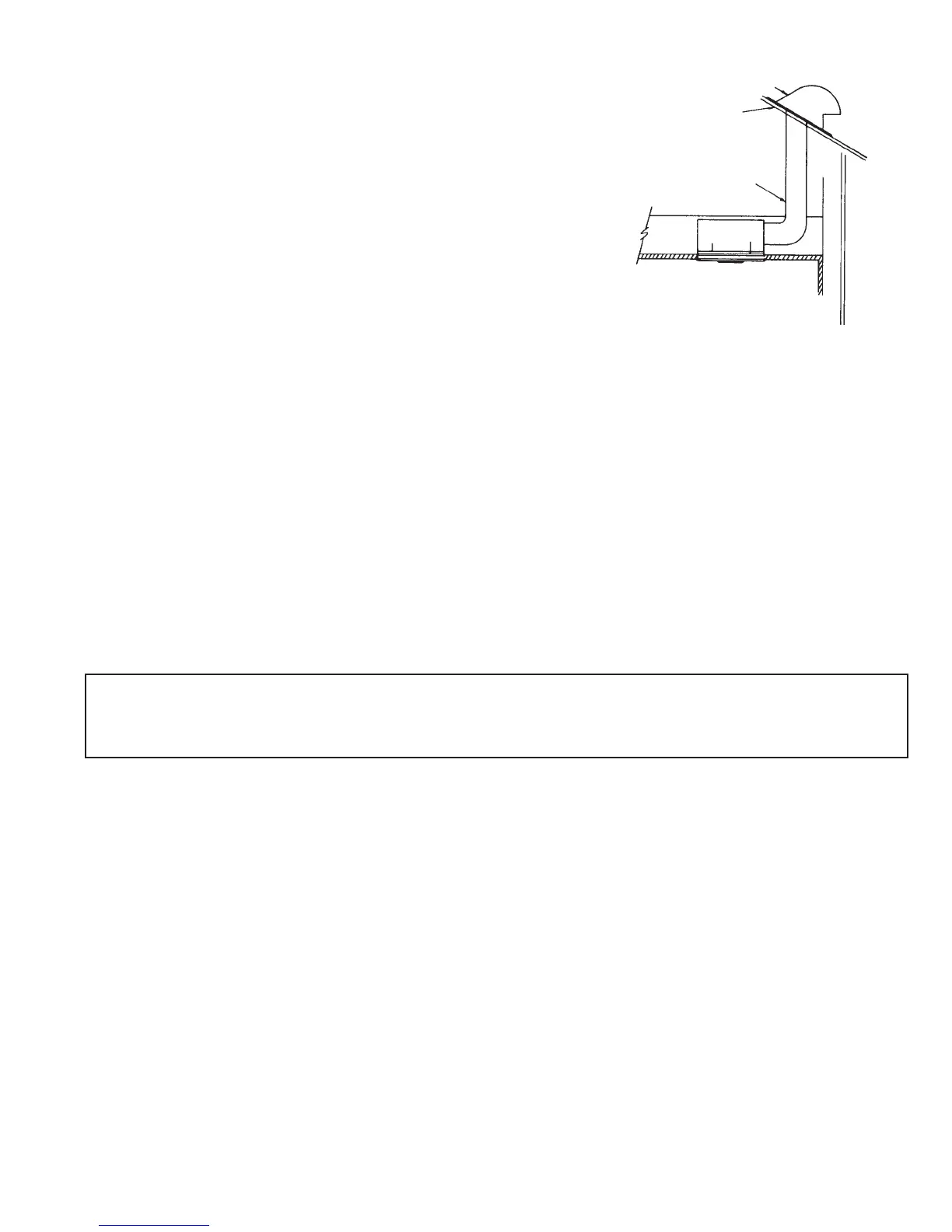
5. Use appropriate size duct for best performance. Model MM648
uses 3” duct. Model MM748, MM748H, A664IC, MM664IC,
MM667IC, and MM667ICF uses 4” duct.
IMPORTANT: Be sure nothing obstructs the discharge of the fan.
Take precautions to ensure that insulation does not get into duct
work or fan discharge opening.
NOTE: Numbers 6 thru 9 apply to models MM664IC, MM667IC and MM667ICF only.
6. Remove lens from grille.
7. Place light plug into receptacle. Align the center hole in the reflector with the threaded screw hole in the grille mounting
bracket. On models MM664IC, MM667IC, AND MM667ICF, align the off-center hole in the reflector with tab on the grille
mounting bracket. Fasten using the screw supplied. See Fig. 1.
8. For models MM664IC and MM667IC, install type A-19, 100 watt (max) light bulb. For model MM667ICF, install one of the
following 13 watt twin tube compact fluorescent lamps:
• Sylvania F13DTT/27K • Phillips PL-C 13W/27/USA
• Osram F13DTT/27K • General Electric F13DBX23T4/SPX27
9. Replace lens.
CAUTION:
BE SURE ALL WIRING COMPLIES WITH LOCAL AND NATIONAL ELECTRICAL CODES.
AND HOUSING IS PROPERLY GROUNDED.
-3-
FIG. 7
ROOF CAP
ROOF
ROUND
DUCT
 Loading...