The following procedure must be followed in order to teach
a new token into channel 1.
NOTE:- Rotary data switch position “E” is used to
program tight window token limits and ‘F’ standard
window token limits.
1.Switch OFF the power to the validator.
2.Set the 4 way DIL teach switches 2, 3 & 4 to ON,
ON & OFF (channel 1) or OFF, ON & ON for
(channel 0)
3.Set rotary data switch to position “F” standard
window limit.
4.Switch ON the power to the product.
(The LED will start flashing).
5.Insert 10 to 20 (minimum 10) of the desired
tokens through the validator.
6.Return the 4 way DIL switches 2, 3 & 4 to
Normal Operation settings.
(LED will stop flashing and stay ON to indicate
success).
If the LED continues to flash OFF a number of
times this indicates a failure to teach the new
token. See LED Assistance Codes table for help
and then restart procedure again.
7.Token is now programmed and ready to use.
(New token information has been stored in coin
channel “1” which is rotary switch position “1”).
Any previous taught token information in this
channel will be overwritten).
NOTE:- If token self teach is successful but token
taught is rejected i.e. gives 3 flashes of the LED, check
that channel “1” is enabled.
To enable the new token set the rotary data switch to
position “1” then refer to enabling coin or tokens
configuration procedure).
-FAuto configuration
-DParallel output ONOFFOFF
-CBinary coded output
Selecting Machine Interface Types
---OFF-Set the alarm OFF
---ON-Set the alarm ON
ONOFFOFF-0 - 7
Change overflow default exit route
ONOFFON-EFraud Defence teach channel 0
OFFONON-
Self teach a token for channel 1
ONONOFF -
Self teach a token for channel 0
OFFONON-0 - DToken group for channel 1
ONONOFF-0 - DToken group for channel 0
OFFOFFON-0 - FEnable a coin or token channel
OFFONOFF-0 - FInhibit a coin or token channel
SW4SW3SW2SW1
2 3 4
ON
1
2 3 4
ON
1
Channel
Position
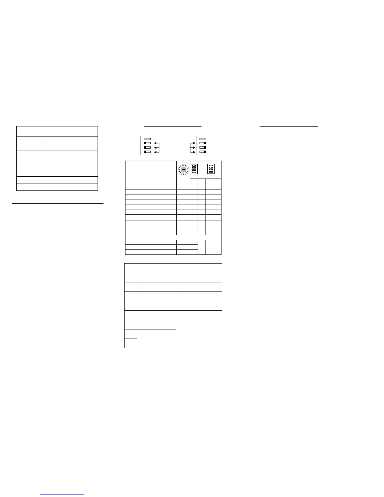
Product Configuration Table
What Do You Want To Do?
w E = Tight Window Limits. Channel F = Standard Window Limits
x 8
Token material outside
acceptable limits
x 7
Token diameter outside
acceptable limits
x 6
Check that there are no mixed
sample tokens
Token thickness outside
acceptable limits
x 5
Ensure that the rotary switch is
set to “F”
Incorrectly set rotary
switch position
x 4
Ensure at least 10 tokens have
been inserted
inserted
x 3
No activity was registered
within 30 seconds
Validator timed outx 2
Reason/ActionDescription
for Code
LED
Flashes
Teaching Token (LED Assistance Codes)
Normal Operation Settings
2 3 4
ON
1
2 3 4
ON
1
Set switches 2, 3 & 4
to ON or OFF
No power to validatorOFF
Validator is set in teach modeFlashing
Coin inhibited by validator or machine4 x Flash
Coin inhibited by validator 3 x Flash
Coin rejected as unrecognised2 x Flash
Reject lever pressed or coin accepted1 x Flash
Power is ON validator is O.K.ON
MEANINGSTATE
What Is The Green LED Doing?
Using 4 Way DIL & Rotary Data Switches
To achieve a successful change to the configuration of the
validator the following procedure must be followed.
1.Switch OFF the power to the validator.
2.Set the 4 way DIL switches to the configuration
settings required. (See Product Configuration
Table)
3.Select the required data / channel position using
the rotary data switch. (see product configuration
table)
4.Switch the validator power ON. (The LED will
start flashing).
5.Return the 4 way DIL teach switches back to
Normal Operation Settings. (Switches 2,3 & 4 set
to all ON or all OFF).
6.The LED will stop flashing and will stay ON. This
will indicate a successful change and that the
validator is ready for normal operation.
NOTE:- If teach is entered by mistake, switch OFF the
power to the validator before moving the 4 way DIL
switch positions else the mech. may learn something
unintentionally.
 Loading...