J
Justin GreenAug 14, 2025
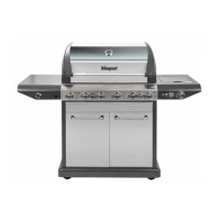
What to do if my Masport SUPREME W 210 Grill burner won’t light after pushing and turning the knobs?
- AAmanda WilliamsAug 14, 2025
If the burner on your Masport Grill won't light after pushing and turning the knobs, there could be several reasons: * The electrode may have cooking residue. If so, use a clean swab and alcohol to clean it. * The electrode might be damaged, in which case it should be replaced. * The electrode wires could be loose or disconnected; reconnect them or replace the electrode assembly with new wires. * The orifice could be blocked; check it for any blockage. * The wire may be shorting; ensure the connections are tight and replace the electrode assembly with new wires if necessary.