EasyManua.ls Logo

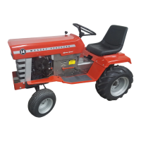
MASSEY FERGUSON MF 14 - Removal; Installation; Transmission Disassembly

MASSEY FERGUSON MF 14
95 pages
To Next Page IconTo Next Page
To Previous Page IconTo Previous Page
Loading...
Two
methods
can
be
used for timing.
One
method
is static
timing;
the
other is
with
a timing
light.
STATIC
TIMING
METHOD
1.
Disconnect
spark
plug
wire to
prevent
engine
starting
and
remove
breaker
point
cover.
2.
Rotate
engine slowly
in
direction
of
nor-
mal
rotation
and
observe
timing
marks
and
the
points.
The
points
should
just
start
to break
as
the
S mark
on
the
flywheel
aligns
with the
mark
on
bearing plate.
lf
marks
do not
align
readjust
point
gap-
The
point
gap
will
vary
from
.01g"-
.022"
. This
can
be
determined
as
follows:
a.
With
a
thin
piece
of cellophane
be-
tween
the
points,
which
can
be
removed
as
TRANSMISSION
REMOVAL
The
rear
axle
and
transmission
should
be
removed
from
the
tractor
as
an assembly.
To
remove proceed
as follows:
1.
Remove
seat
and
fenders
as
an assem-
blv.
2.
Remove
dress
panels
over
drive shaft
and
fan.
3. Disconnect
light
wires.
4.
Disconnect
brake
rod
at
rear.
5.
Disconnect
transmission
control
rod
at
front
end.
6.
Remove
bolts
from
each side
of
tractor
as indicated
by
arrows
in
Figs.
18
and 19.
7.
Raise
tractor
frame
and
roll transmission
and
rear
axle
out.
INSTALLATION
1.
Raise
tractor
frame
and
roll
transmis-
sion
and
rear
axle into
place.
2.
lnstall
bolts
at
each side
of the tractor.
3.
Connect
brake
and
transmission
control
rods.
4.
Connect
light
wires.
5.
lnstall
dress
panels
over
drive shaft
and
install
seat
and
fenders.
TRANSM
ISSION
DISASSEM
BLY
Two
different
versions
of
the charging pump
are
used in
the
transmission.
The
se'rvi6e
pro-
cedures
of
the
transmission
are
basically'the
same
except
the charging pump
area.
One
type
is
a
plain
casting
bore
for
the
iump
shaft
beir-
ing
and
the
other
has
a ball
bearing
in
the
cast-
ing.
See
Fig. 20.
the
points
just
start
to
open.
b.
Connect
a
continuity
test light
to
the
point
wire
and
to
ground,
as shown
in
Fig. 17.
Rotate
engine
slowly
in
the
direction
of rota-
tion
until light
just
goes
out. At
this
point
S
mark
on
flywheel
should
align
with
mark on
bearing
plate.
TIMING
LIGHT
METHOD
1.
Hook
up timing light
in
accordance
with
manufacturer's
recommendation.
2.
Chalk
mark
S mark on
flywheel.
3.
Start
engine
and aim
timing light
at hole
in
flywheel
cover.
Timing
marks should
align
when light
flashes.
Adjust
points
to change
tim-
ing.
AND
REAR AXLE
Fig. 20
-
Charging
Pump
Housings
Fig.
18
-
Right-Hand
Side
of Tractor
Fig. 19
-
Left-Hand
Side ol Tractor
-9-

Related product manuals