Master Audio
PRO Series.Version 1.5 Nov10
32
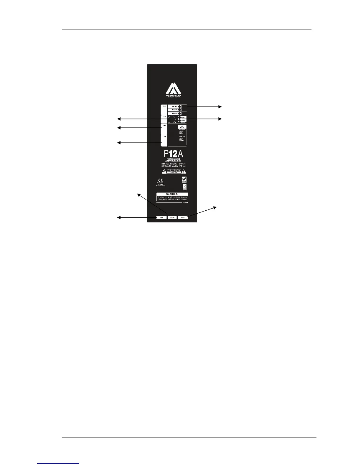
2-P26A / P10A / P12A / P15A / P212A CONNECTIONS
5
1 6
2
3
4
8
7
Fig.1.
Panel
1 - GAIN: Controls the level of the LINE Input
2 - INPUT: Balanced signal XLR:
1= Shield 2= Live 3= Return
3 - LINK: XLR connector used for paralleling several units, which will share the
same input.
1= Shield 2= Live 3= Return
4 - FUSE
5 - MODE SWITCH :
Full Range / 90Hz Filter
6 - LIMITER: Prevents the amplifier outputs from overdriving the transducers. When
the LIMITER indicators are active, they are in red colour. The LIMITER indicators can
be in red occasionally, but if they are continuously activated, turn down the level
control until the LIMITER indicators are only in red occasionally.
7 - LINK (MAINS) : Output AC PowerCon to feed a secondary cabinet
8 - INPUT(MAINS): Input AC PowerCon connector.