3
IT
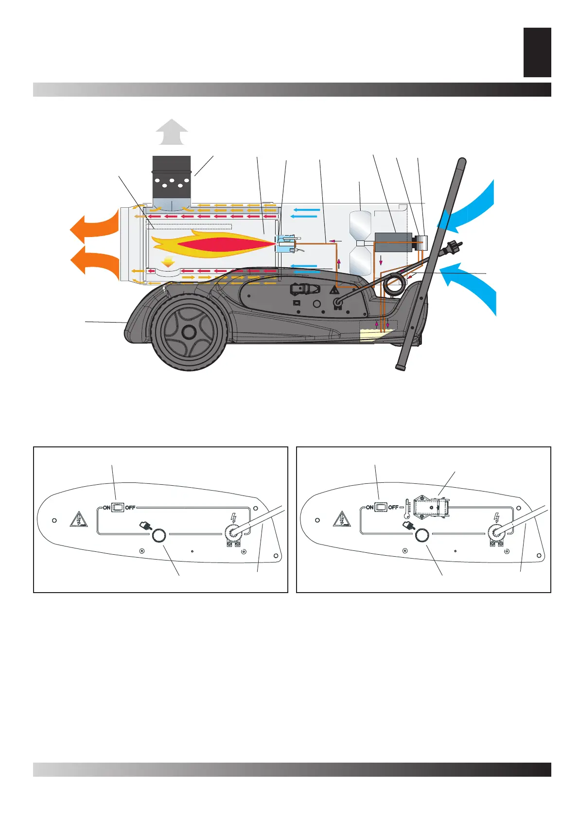
1. Camera di combustione, 2. Raccordo fumario anti vento, 3. Bruciatore, 4. Ugello, 5. Circuito combustibile, 6. Elettrovalvola combu-
stibile, 7. Pompa, 8. Motore, 9. Ventola, 10. Filtro combustibile, 11. Serbatoio.
Figura 1
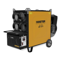
1. Interruttore principale, 2. Pulsante reset, 3. Cavo di alimentazione, 4. Presa per termostato ambiente.
Figura 2 (A - B)
QUADRO ELETTRICO
PRINCIPIO DI FUNZIONAMENTO