The Mate Logo is a registered trademark of Mate Precision Tooling Inc.
Mate Precision Tooling • 1295 Lund Boulevard • Anoka, Minnesota 55303 USA • Phone 763.421.0230 • 800.328.4492 • Fax 763.421.0285 • 800.541.0285
Dimensions in Inches(millimeters) mate.com
LIT00366 Rev C
Mate Pilot™ Turret Calibration System
Installation and Operation Instructions
Storage Instructions
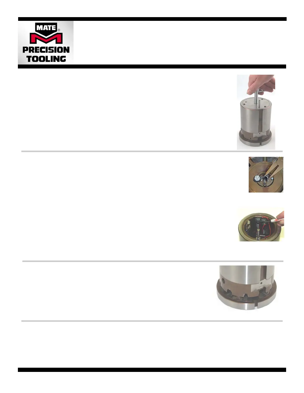
1. Separate the upper from the lower by unscrewing the adjustment handle.
2. Remove the batteries if storage for longer than three (3) months is expected. See battery installation instructions.
3. Coat the lower with a spray lubricant/preservative or light machine oil. Examples: LPS 1, WD-40.
4. Wipe off any excess lubricant/preservative from the sensor contact surface.
5. Re-assemble the lower and upper aligning the external orientation slots, and tighten the handle until the light glows green.
6. Coat the outside surface of the upper instrument with the lubricant/preservative.
7. Loosen the handle and position the upper and lower with the interlocking teeth disengaged to prevent inadvertent
activation of the indicator light during storage. See photo at right.
8. Tighten the handle using the tensioning knob until a click is felt.
Battery Removal and Installation
1. Separate the upper from the lower by unscrewing the adjustment handle.
2. Remove the clip which secures the adjustment handle to the upper with a screwdriver. Be careful not to
damage the sensors.
3. Remove handle from the upper assembly.
4. Unscrew the button head screws on the cover. Use 2mm hex wench for 1-1/4” B station. Use 2.5mm hex
wrench for 2” C, 3-1/2” D, and 4-1/2” E Stations
. Remove the cover and set aside.
5. Remove old batteries.
6. Install new batteries paying attention to polarity.—Locate the negative (-) of the battery against the spring in
the battery pack first. Then compress the spring with the battery, and slide battery into the battery pack until
the positive (+) end of the battery touches the end contact.
7. Test the operation of the batteries. Gently lower the upper instrument on to the lower instrument until the
interlocking teeth are fully engaged. If the light fails to activate, repeat steps 5 and 6.
8. Reinstall the cover, using the button head screws and wrench used in step 4.
9. Reinstall the adjustment handle. Install the handle through the upper instrument until the tip protrudes
through the underside. Replace the clip into the groove on the adjustment handle. Use needle nose pliers
to guide the ears of the clip into the slot until is snaps into position.
Removal and Reinstallation of Adjustment Handle.
• Remove the clip using a flat bladed
screw driver to pry out the retaining
clip. Take care not to damage the
sensors located around the handle
• Replace the clip using needle nose
pliers to guide the ears of the clip
into the slot on the handle until it
snaps into position.
• Pry the first battery out by
placing the tip of a flat
bladed screwdriver under
the top lip of the battery
holder and on top of the
flat of the battery.
• Pry the second battery out
by placing the tip of a flat
bladed screwdriver behind
the body of the battery.
Battery Removal 2” C, 3-1/2” D and 4-1/2” E Stations
Preparation for Use
1. Separate the upper from the lower by unscrewing the adjustment handle.
2. Ensure that the serial number of both the upper and lower instruments are identical.
3. Wipe off any lubrication/preservative oil from the unit with a soft cloth paying close attention to the interlocking teeth. Compressed air may be
used; care should be taken not to blow air in the sensor area. Always blow from the inside to the outside.
4. Install the batteries (if applicable). See Battery Removal and Installation.
5. Re-assemble the upper and lower by tightening with the tensioning knob.
6. Check the color of the tri-color indicator light.
• No light—check battery installation. Replace battery if required. See section below.
• Red or Yellow—interlocking teeth may be dirty. Clean interlocking teeth and recheck.
• Green—calibration system is operational and ready form immediate use.
Note: If you cannot get the light to turn green by using the tension knob only and the parts are clean, the unit may be out of adjustment. Contact
Mate Precision Tooling for immediate assistance.
Pilot is a trademark of Mate Precision Tooling Inc.
 Loading...