3
MATelec Australia reserves the right to alter technical data without notice
Warning: All electrical connections must be carried out by a suitably
qualified and registered electrician
Step 2 - Connections
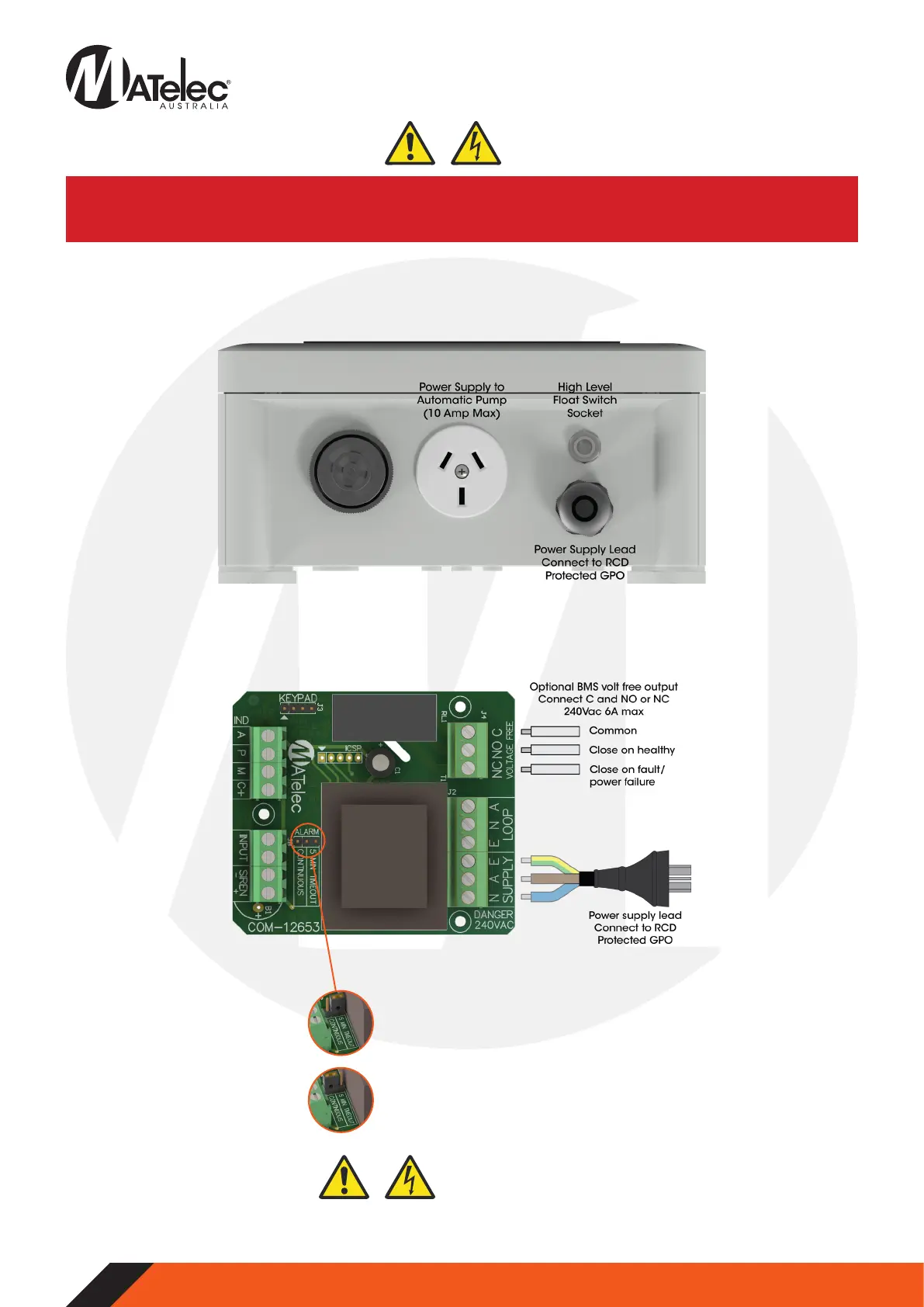
2.1 - Quick Plug Connections
• Connect the float switch to the quick plug socket on the underside of the panel.
• Connect the automatic pump (10 Amp max) to the GPO on the underside of the panel.
2.2 - Control Module Connections
• Connect to volt free output if required. If connected to ‘C’ and ‘NO’ terminals, the output will close when the alarm is inactive
and open when active or on power failure. If connected to ‘C’ and ‘NC’ terminals, the output will close when the alarm is active
or on power failure.
Close and secure enclosure door, connect the power lead into RCD protected GPO and switch on mains power.
If this jumper is left on the ‘5 Min Timeout’
position, the buzzer will automatically
silence after 5 minutes if not muted, then
chirp briefly every 5 seconds.
If a continuously sounding alarm is required,
switch this jumper to the ‘Continuous’
position.
2.3 - Alarm Jumper Position
Step 3 - Powerup
 Loading...