6
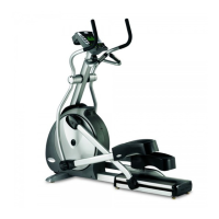
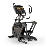
E50
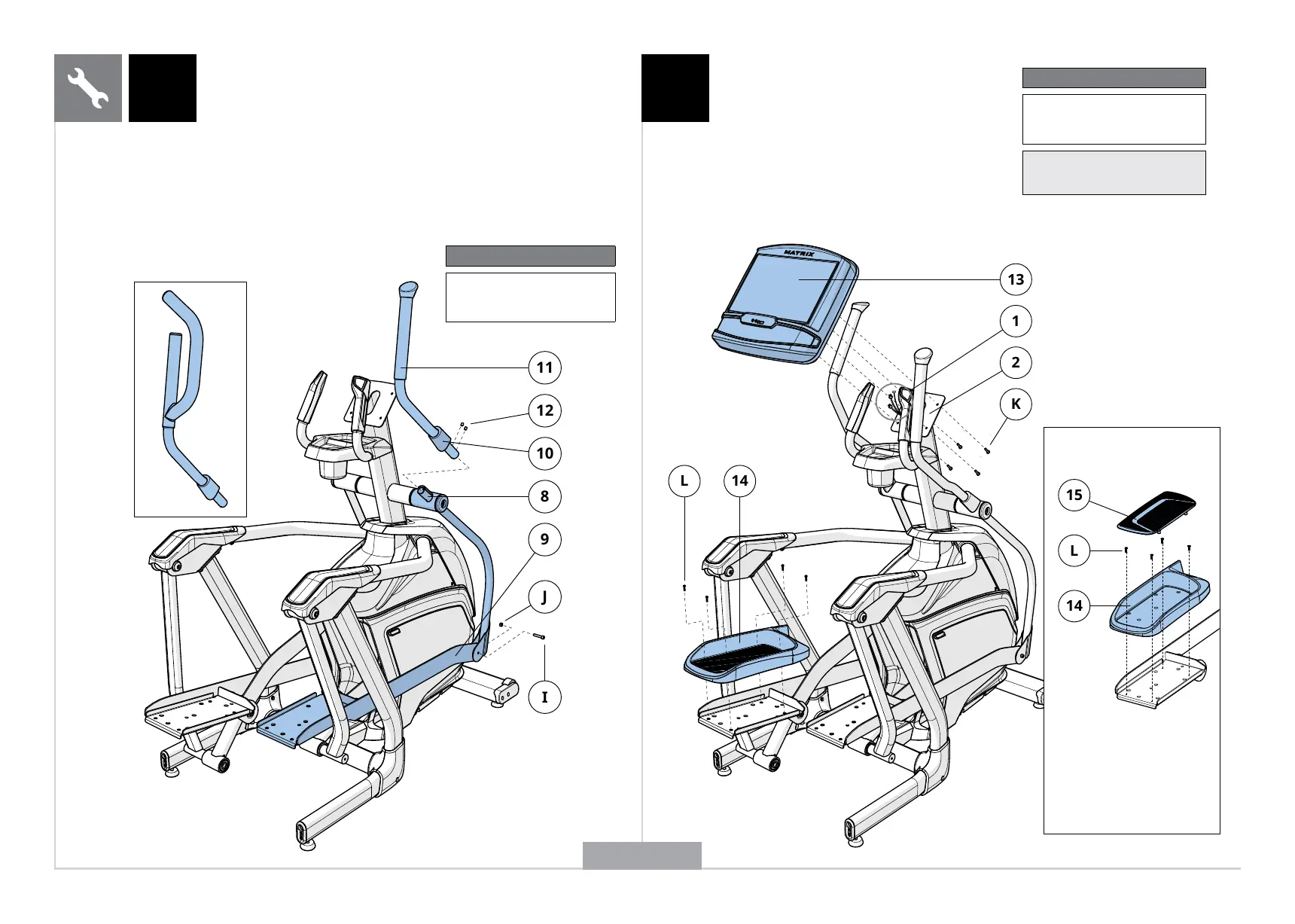
A Open HARDWARE FOR STEP 3.
B Attach the LINK ARM (9) to the LOWER DUAL
ACTION ARM (8) using 1 BOLT (I). 1 NUT (J).
C Slide the HANDLEBAR BOOT (10) halfway up the UPPER
DUAL ACTION ARM (11). Loosen PRE-ATTACHED SET
SCREWS (12) before sliding the UPPER DUAL ACTION
ARM (11) onto the LOWER DUAL ACTION ARM (8). Make
sure handlebars are joined together completely.
D Secure the UPPER DUAL ACTION ARM (11)
using PRE-ATTACHED SET SCREWS (12).
E Repeat steps B–D on other side.
3 4
Hardware For Step 3
Description Qty
I
J
Bolt
Nut
2
2
A Open HARDWARE FOR STEP 4.
B Connect the CABLES (1) to the CONSOLE
(13) and carefully tuck the excess
cable into the CONSOLE MAST (2).
C Attach the CONSOLE (13) to the
CONSOLE MAST (2) using 4 BOLTS (K).
D Attach PEDAL (14) to LINK ARM (9) using
4 SCREWS (L). Repeat on other side.*
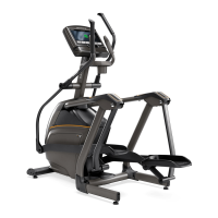
E30 SHOWN
Hardware For Step 4
Description Qty
K
L
Bolt
Screw
4
8
Note: Be careful not to pinch any
wires while attaching the console.
Attach PEDAL (14) to
LINK ARM (9) using 4
SCREWS (L). Snap PEDAL
INSERT (15) into pedal.
Repeat on other side.
*
E50
ENGLISH