This document provides installation instructions and an owner's manual for MAVIMARE & MANCINI hydraulic steering systems, designed for marine applications. The systems are certified CE by the Italian Shipping Register (Rina) in conformity with the 2013/53/EU rule.
Function Description
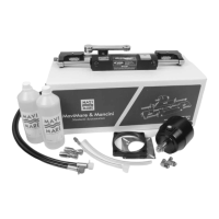
MAVIMARE & MANCINI hydraulic steering systems are designed to provide precise and reliable steering for various types of boats, including those with outboard, inboard, and stern drive engines, as well as catamarans. The system operates by using hydraulic fluid to transmit steering commands from the helm pump to the cylinder, which then moves the engine or rudder. This allows for smooth and effortless control of the vessel. The manual covers various configurations, including single and double cylinder setups, and applications with tie bars for twin and triple engine installations.
Important Technical Specifications
The manual details several cylinder types and their corresponding specifications. For example, the CE30, CE50, CE75, and CE100 cylinders are designed for inboard steering systems, with varying dimensions and capacities. The MC150, MC90B, MC150BR, MC150R - MC300R, MC300BHD - MC300HD, MC300BE, MC350HD, MC350HD double cylinder, and CE50S cylinders are designed for outboard and stern drive applications.
Hydraulic Fluid:
- MAVIMARE HYDRAULIC FLUID SHELL TELLUS T15 (CL T15 HIV) is the recommended oil.
- Viscosity: 15 cst
- Viscosity index: 142
- Solidification point: C° -38
- Note: Automatic transmission fluid Dexron II may be used in case of emergency. Non-approved fluid may cause irreparable damage, loss of steering, and loss of warranty coverage.
Helm Pumps:
The manual references various helm pumps such as GM2-MRA01, GM2-MRA03, GM2-MRA04, and GM2-MRA05, which are suitable for different applications. These pumps typically require 4-5 bottles of oil for filling.
Minimum Splashwell Dimensions:
For proper installation, specific minimum splashwell dimensions are required, varying based on the number of engines. For a single engine, the dimensions are A: 560mm (22.05"), B: 152mm (5.98"), C: 152mm (5.98"). For two engines, these increase to A: 1110mm (43.70"), B: 152mm (5.98"), C: 152mm (5.98").
Cylinder Types and Capacities (examples from Technical Information table):
| Type |
PUMPS |
N° OF PISTONS |
TURNS OF WHEEL |
CAPACITY MAX |
MAX PRESSURE BARS |
CYLINDERS |
BORE Ø [mm] |
VOLUME CM³ |
STROKE [mm] |
| GE30 |
GM2MRA01 |
7 |
3.9 |
33 |
60 |
CE30 |
28 |
62 |
150 |
| GE50 |
GM2MRA01 |
7 |
3.3 |
43 |
60 |
CE50 |
32 |
90 |
150 |
| GE75 |
GM2MRA01 |
7 |
6.3 |
68 |
60 |
CE75 |
40 |
118 |
215 |
| GE100 |
GM2MRA01 |
7 |
3.3 |
100 |
60 |
CE100 |
40 |
202 |
200 |
| GF150 |
GM2MRA01 |
7 |
3.3 |
43 |
60 |
MC150E |
32 |
88 |
200 |
| GF150R |
GM2MRA01 |
7 |
5.2 |
52 |
60 |
MC150R |
32 |
83 |
200 |
| GF150BR |
GM2MRA01 |
7 |
4.8 |
52 |
60 |
MC150BR |
32 |
83 |
200 |
| GF300BHD |
GM2MRA01 |
7 |
2.7 |
27 |
60 |
MC300BHD |
28 |
34 |
200 |
| GF300R |
GM2MRA01 |
7 |
3.1 |
27 |
60 |
MC300R |
28 |
34 |
200 |
| GF300BE |
GM2MRA01 |
7 |
4.9 |
27 |
60 |
MC300BE |
28 |
34 |
200 |
Usage Features
Installation:
- General Safety: Always follow instructions, use qualified technicians, and ensure all parts are installed correctly.
- Helm Pump Installation: Select a suitable position for the steering pump and wheel. Ensure adequate space for the steering wheel and that the helm pump unit is horizontal. The filler plug must always be in the uppermost position.
- Cylinder Installation: Specific instructions are provided for various cylinder types (MC150, MC90B, MC150BR, MC150R - MC300R, MC300BHD - MC300HD, MC300BE, CE50S). These include details on attaching the extension rod, adjusting nuts, and connecting to the tiller arm.
- Hose Installation: Route hoses via the shortest path to avoid power loss. Ensure hoses are protected from chafing and heat. Use suitable bulkhead connectors or sleevers. Hoses should be cut with a sharp knife, not a saw, to prevent nylon fragments from entering the system.
- Ground Strap Installation: For saltwater applications, a ground strap is strongly recommended to protect against corrosion caused by stray current. It should be routed under the tilt tube and connected to the lower midesection steering bracket hole.
- Tie Bar Installation: For twin and triple engine applications, tie bars (e.g., code 358.02, 358.08, 358.09, 358.10) are used to synchronize engine movement. Proper alignment and clearance are crucial to prevent damage during tilting.
- Filling and Purging: The system must be filled with hydraulic fluid and purged of air. This involves filling the helm pump, turning the steering wheel to full lock in both directions, and bleeding air from the cylinder. Specific procedures are outlined for single and dual station systems, and for single and twin cylinder configurations.
Troubleshooting:
The manual includes a comprehensive troubleshooting guide for common issues such as:
- Lumpy or Notchy Steering: Often caused by air in the system or incorrect tubing type/pressure.
- Oil Overflowing: Usually due to overfilling the pump unit.
- Tight Steering: Can be caused by air in the system, storage of pressure, mechanical interference, or overtightened nuts.
- Steering Slipping: Indicates air in the system or worn internal components.
- Faults and Solutions Table: Provides a detailed list of common faults, their causes, and solutions (e.g., "During filling the helm becomes completely jammed" -> "Lockage in the line between the helm(s) and the cylinder(s)" -> "Make certain that hoses are not collapsed during installation. In this case replace hoses. The damaged hose must be replaced. Otherwise it may cause loss of steering and severe personal injury or property damage.").
Maintenance Features
Regular Checks:
- Every 3 months (or every month for professional uses): Check the right torque of the bolt and self-locking nut.
- Periodically: Check fluid level in the helm pump.
- Visually inspect: Steering wheel(s) for very immediate steering response, all steering hoses and fittings for wear, kinking, and/or leaks.
- Check: For binding, loose, worn, or leaking steering components.
Maintenance Schedule (from Technical Information table):
- Check after 20 hours / 100 hours (whichever comes first):
- All points noted above.
- Check all fasteners/fittings throughout the steering system.
- Check for mechanical play or slop throughout the steering system.
- Check for signs of corrosion.
- Check after 200 hours / 12 months (whichever comes first):
- All points noted above.
- Remove support rod from engine/tilt tube.
- Clean engine steering/tilt tube and re-grease using a good quality marine grease.
- Grease support rod liberally.
- Grease all contact points shown in the cylinder and tiebar installations.
- DO NOT remove tiller bolt to re-grease.
- Remove steering wheel and re-grease wheel shaft using a good quality marine grease.
- Inspect hydraulic oil for cleanliness, flush if required.
Important Notes:
- DO NOT use brake fluid. It will damage seals and other components. Use only MAVIMARE SHELL TELLUS T15 HYDRAULIC OIL.
- DO NOT re-use oil from bleeding the system without first filtering it to remove foreign material.
- DO NOT use automatic transmission fluid.
- Ensure the engine is properly grounded in saltwater applications to prevent corrosion.
- All systems are not intended for racing boat application.