• Turn on the supply socket outlets.
• To set the time, remove the clear front cover from the timer and rotate the minute hand until the correct time is
reached. Ensure that the front cover is refitted correctly.
• e timer has a three position overrride switch:
In position ‘I’ the output sockets will be switched on at all times
irrespective of the timer settings.
In position ‘O’ the output sockets will be switched off at all times
irrespective of the timer settings.
In position ‘
‘ the output sockets will be switched on or off in
accordance with the timer settings.
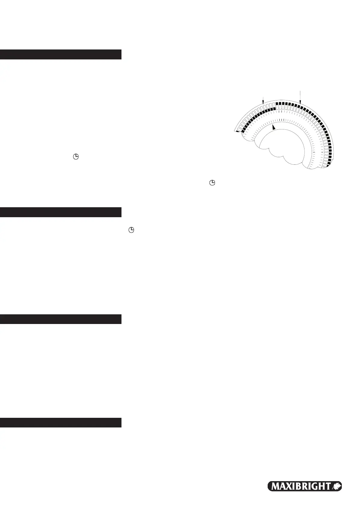
e time that sockets are required to be switched ‘ON’ when in the
‘ ’ position is set by moving the tappets to the
outer position for the required period. (See Fig.1)
Disposal
is unit is not suitable for disposal as or with household waste. It should be taken to a local recycling centre.
• Maxibright Maxiswitch Pro units carry a 2 year guarantee (terms & conditions apply), excluding faulty fuses
and tampering .
• In the unlikely event that you find fault with this product, please contact your supplier.
e manufacturer shall not be responsible for any damage caused by operation of the unit, be it incidental or
consequential; or of any type; including, without limitation, damage or injury, caused to other products, machinery,
or buildings. Nor will responsibility be accepted for loss of time or profit, loss of finished product, or for any
inconvenience caused in any way whatsoever.
MAXISWITCH PRO
Rev. 1.01
www.maxiswitch.co.uk
• Ensure that the timer switch is in the ‘ ‘ position and rotate the clock face until the unit is in an ‘ON’ position
where the sockets should always be on.
• Plug in a device that is known to be working and turn on
.
• If this does not power the unit, disconnect from the mains and
check the fuses in the plugs.
Replace if necessary, ensuring the same type and rating of fuse is fitted.
• Re-connect the unit to the mains and retry the known working device
.
• If this still does not power the unit please contact your supplier.
5
6
7
8
9
10
11
12
13
14
15
16
Tappets in OFF position
Tappets in ON position
Fig. 1
e
Operation
Troubleshooting
2/4/6/8 WAY
IT CONTROL UNIT

 Loading...