Warning: Do not connect external voltage
source to the connectors!
Frequency
Range Accuracy Resolution
10 Hz
+/-(1.0%+10)
0.001Hz
100 Hz 0.01 Hz
1 kHz 0.1Hz
10 kHz 1 Hz
100 kHz 10 Hz
1 MHz 100 Hz
Inward sensitivity 1 V RMS
Overload protection
250 V DC / AC RMS
(for maximum 15
seconds)
Transistor hFE test
Function Description Test state
h
FE
The
amplication
factor of the
transistor is
measured (0-
1000)
(all types)
Base current
appr. 10 μA
V
CE
appr. 3 V
Contact phase detection function
• Set the function switch to TEST position.
• Connect the red measuring wire to the V
connector.
• Touch the wire to the measured point, BUT
MAKE SURE YOUR FINGERS ARE BEHIND THE
FINGER PROTECTION PART AT ALL TIMES!
If phase is present, the device gives a continuous beeping
sound, the red light beneath the HOLD button lights up
and the display shows ’1’. If there is no phase, the device
displays ’000’.
IMPORTANT!
• Make sure that when measuring the above the
function switch is ALWAYS in TEST state!
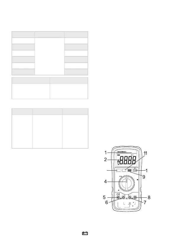
Usage
•Check the 9V battery and press the POWER
button. If the battery is depleted, the
symbol appears on the screen.
• The signs near the connectors warn about not
exceeding the inward voltage or current. This is
to prevent damage to the inside circuits.
• Set the function switch to the desired
resistance range.
• If you are unsure about the magnitude of the
result, set the switch to the highest possible
range and go backwards until you reach the
correct setting.
DC and AC voltage measuring
• Connect the black measuring wire to the „COM”
and the red one to the „V/ Ω /Hz” connector.
• Set the function switch to the correct V position
and connect the wires to the voltage source
paralelly.
Note:
• If you are unsure about the magnitude of the result,
set the switch to the highest possible range and go
backwards until you reach the correct setting.
• If only a „1” is displayed on the screen, it signals overload.
Switch to a higher range.
• Do not connect voltage exceeding DC 1000V or AC 750V
to the connectors! Results may be displayed at higher
voltages also, but this may lead to damage to the inside
circuits.
• Do not touch the high voltage circuits while measuring.
MX-25 302
AUTO
POWER
OFF
NPNE B C E
E B C E
PNP
V
V
~
A
~
V HZ
20A mA COM
A
F
hFE
20V
20V
2V
2V
200V
200V
750V
200
Ω
2kΩ
20kΩ
200kΩ
200kHz
200µF
2µF
20nF
20mA
200mA
20A
20A
200mA
20mA
TEST
2k
Hz
2MΩ
200MΩ
200mV
1000V
°C
MAX
200mA
FUS E D
MAX
1000V DC
750V AC
10 secMA X
20A
FUS E D
Ω
Ω
HOLD B/LPOWER APO
TEMP
CAT
3
10
DC
T-RMS
MAX
MIN
AC
APO
REL hFE
HOLD
LED
m
u
V
F
F
%
C
˚˚
Mk Hz
Ω
n
A
+
-
 Loading...