ENGLISH
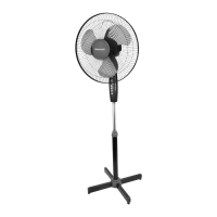
FAN MW-3540
The fan is intended for artificial ventilation of
the room
FAN DESCRIPTION
1.
Front safety grid
2.
Plastic blade clamp
3.
Clamp ring
4.
Fastening screw
5.
Blades
6.
Rear grid plastic fastening nut
7.
Rear grid
8.
Fan carrying handle
9.
Motor axis
10.
Control panel
11.
Oscillation On/Off button
12.
Motor unit
13.
Motor unit clamp
14.
Telescopic bar
15.
Telescopic bar clamp
16.
Decorative panel
17.
Supports
18.
Fastening screws
SAFETY MEASURES
Before using the electrical appliance, read this
instruction manual carefully, and keep it for
further reference.
Use the unit for intended purposes only, as
specified in this manual. Mishandling the unit
can lead to its breakage and cause harm to the
user or damage to his/her property.
• Before switching the unit on for the first time,
make sure that your home mains voltage
corresponds to unit operating voltage.
• Before using the unit, examine the power
cord closely and make sure that it is not
damaged. If you find that the power cord is
damaged, do not use the unit.
• Do not use the fan outdoors.
• Place the unit on a flat, dry and steady sur-
face away from sources of heat or open
flame.
• Do not use the unit near containers filled
with water, next to a kitchen sink, in wet
basements or near a swimming pool.
• Do not immerse the fan, power cord and
power plug into water or any other liquids.
• Do not touch the unit body and the power
plug with wet hands.
• If the fan falls into water, unplug it
before touching it and only then you
may take the fan out of water. Apply
to the nearest authorized service cen-
ter for testing or repairing the unit at
the contact addresses given in the war-
ranty certificate and on the website
www.maxwell-products.ru.
• Make sure that the power cord does not
contact with hot surfaces and sharp furni-
ture edges.
• Do not switch the unassembled fan on.
• Do not insert any foreign objects into the
openings of the fan protective grids to avoid
injuries or unit damage.
• Do not touch the rotating blades during the
fan operation.
• Do not place the fan near curtains or house
plants.
• It is not recommended to stay under the
air flow coming from the fan for a long time
(especially for children and elderly people).
• Do not leave the operating unit unattended.
• Unplug the fan before cleaning and when
you do not use the unit or before moving it
to a new place.
• When unplugging the fan, pull the plug but
not the cord.
• Clean the unit regularly.
• Do not leave children unattended to prevent
using the unit as a toy.
• For children safety reasons do not leave
polyethylene bags, used as packaging,
unattended.
ATTENTION! Do not allow children to play with
polyethylene bags or packaging film. Danger
of suffocation!
• Do not allow children to touch the unit
body and the power cord during the unit
operation.
• The unit is not intended for usage by physi-
cally or mentally disabled persons (includ-
ing children) or by persons lacking experi-
ence or knowledge if they are not under
supervision of a person who is responsible
for their safety or if they are not instructed by
this person on the usage of the unit.
• If the power cord is damaged, it should be
replaced by the manufacturer, a mainte-
nance service or similar qualified personnel
to avoid danger.
• Do not attempt to repair the unit. Do not
disassemble the unit by yourself, if any mal-
function is detected or after it was dropped,
unplug the unit and apply to any authorized
service center at the contact addresses
given in the warranty certificate and on the
website www.maxwell-products.ru.
• Transport the unit in the original package.
• Keep the unit in a dry cool place out of
reach of children and disabled persons.
THE UNIT IS INTENDED FOR HOUSEHOLD USE
ONLY, ITS COMMERCIAL USAGE AND USAGE
IN PRODUCTION AREAS AND WORK SPACES
IS PROHIBITED.
BEFORE THE FIRST USE
After unit transportation or storage at low
temperature keep it for at least three hours
at room temperature.
The fan is supplied disassembled. Do not
switch the fan on until it is completely
assembled.
• Unpack the unit and remove any stickers
that can prevent its operation.
• Check the unit for damages, do not use it in
case of damages.
• Set the supports (17) crosswise on a flat
dry surface.
• Set the telescopic bar (14) on the supports
(17) and fix it with four fastening screws (18).
• Screw out the clamp (15) by rotating it
counterclockwise. After removing the clamp
(15), set the decorative panel (16) on the
telescopic bar (14). Set the clamp (15)
back to its place by turning it clockwise for
several times.
• Extend the bar (14) to the desired height
and fix it by tightening the clamp (15) with a
slight effort as you turn it clockwise.
• Install the motor unit (12) on the telescopic
bar (14) until bumping and fix it by the clamp
(13), do not apply excessive effort when
screwing the clamp of the motor unit (13).
• Set the rear grid (7) on the motor unit (12)
matching the guides on the motor unit (12) with
the corresponding openings on the grid (7).
• The carrying handle (8) on the rear grid (7)
should be turned upwards. Fix the rear
grid (7) on the motor unit (12) with the plas-
tic nut (6) by screwing it clockwise until
bumping.
• Put the blades (5) on the motor axis (7) match-
ing the groove on the blades with the clamp
on the motor axis and fix them with the plas-
tic clamp (2) rotating it counterclockwise and
holding the blades (5) with your free hand.
• Set the nut and the fixing screw (4) into the
clamp ring (3) sockets.
• Match the front grid (1) and the rear
grid (7), fix them with the clamp ring (3) and
tighten up the clamp ring (3) by turning the
fixing screw (4) tight.
Note! For easy grid assembling of the fan first
install the clamp ring (3) on the rear grid (7)
and tighten up the fastening screw (4) slightly.
Install the bottom part of the front grid (1) on
the clamp ring (3). Then press the bottom part
of the front grid (1) to the clamp ring (3) and
squeezing both grids on the both sides install
the grid (1) under the clamp ring (3). Tighten
the fastening screw (4).
• The fan is ready for operation.
USING THE FAN
• Make sure that the voltage of the mains
corresponds to the operating voltage of
the unit.
• Make sure that the fan is switched off by
pressing the “0” button on the control
panel (10).
• You can change the tilt angle of the motor
unit (12). Turn the clamp counterclockwise
to loosen it and set the desired tilt angle of
the motor unit (12), fix the selected tilt angle
turning the clamp clockwise.
• Insert the power plug into the mains socket.
• Select the required rotation speed of the
blades (5) by pressing buttons on the con-
trol panel (10):
“0” – fan is switched off;
“1” – low blades rotation speed;
“2” – medium blades rotation speed;
“3” – high blades rotation speed;
• Press the button (11) to switch horizontal
rotation of the motor unit on. To switch the
rotation off, pull the button (11) upwards.
• Press the “0” button (the fan is switched off)
to switch the unit off.
• Remove the power plug from the mains socket.
CLEANING AND CARE
• Switch the unit off and unplug it.
• Never use liquid detergents and abrasives
to clean the fan.
• Wipe the unit with a soft dry cloth.
• To clean the blades, remove the front grid (1),
having previously loosened the fixing
screw (4) and removed the clamp ring (3).
Unscrew the blades clamp (2), rotating it
clockwise and remove the blades (5).
• Clean the blades (5) with a slightly damp
cloth and then wipe them dry.
• Assemble the fan following the assembling
instructions in the «Before the first use»
chapter.
• Do not immerse the motor unit (12), the
power cord and the plug into water or any
other liquids.
STORAGE
• Disconnect the unit from the mains and
clean it.
• If necessary, dismantle the fan. Remove
the clamp ring (3), preliminary loosening
the fastening screw (4), the front grid (1)
and then the blades (5) by rotating the
blades clamp (2) clockwise. Unscrew the
plastic nut (6) turning it counterclockwise
and remove the rear grid (7) from the motor
unit (12).
• Remove the motor unit (12) from the tele-
scopic bar (14). Screw out the clamp (15) by
rotating it counterclockwise. After remov-
ing the clamp (15), remove the decora-
tive panel (16) from the telescopic bar (14).
Unscrew the fastening screws (18) and
disconnect the telescopic bar (14) from
the supports (17). Disconnect the sup-
ports (17).
• Put the fan into the box.
• Keep the unit in a dry cool place out of
reach of children and disabled persons.
DELIVERY SET
Motor unit – 1 pc.
Front grid – 1 pc.
Clamp ring with the screw and nut – 1 pc.
Blade clamp – 1 pc.
Blades – 1 pc.
Rear grid – 1 pc.
Telescopic bar with clamp
and decorative panel – 1 pc.
Supports – 2 pcs.
Screw – 4 pcs.
Instruction manual – 1 pc.
TECHNICAL SPECIFICATIONS
Power supply: 220-240 V ~ 50-60 Hz
Rated input power: 35 W
Diameter: 40 cm (16”)
RECYCLING
For environment protection do not throw out
the unit and the batteries (if included), do not
discard the unit and the batteries with usual
household waste after the service life expiration;
apply to specialized centers for further recycling.
The waste generated during the disposal of
the unit is subject to mandatory collection and
consequent disposal in the prescribed manner.
For further information about recycling of this
product apply to a local municipal administra-
tion, a disposal service or to the shop where you
purchased this product.
The manufacturer preserves the right to
change design, structure and specifications
not affecting general principles of the unit
operation without a preliminary notification due
to which insignificant differences between the
manual and product may be observed. If the
user reveals such differences, please report
them via e-mail info@maxwell-products.ru for
receipt of an updated manual.
Unit operating life is 3 years
Guarantee
Details regarding guarantee conditions can be
obtained from the dealer from whom the appli-
ance was purchased. The bill of sale or receipt
must be produced when making any claim
under the terms of this guarantee.
This product conforms to the EMC
Directive 2014/30/EU and to the
Low Voltage Directive 2014/35/EU.
Вентилятор
MW-3540
4
RUS
Дата производства изделия указана в серийном номере на табличке с техническими
данными. Серийный номер представляет собой одиннадцатизначное число, первые
четыре цифры которого обозначают дату производства. Например, серийный номер
0606ххххххх означает, что изделие было произведено в июне (шестой месяц) 2006 года.
GB
A production date of the item is indicated in the serial number on the technical data plate.
A serial number is an eleven-unit number, with the first four figures indicating the production
date. For example, serial number 0606ххххххх means that the item was manufactured in June
(the sixth month) 2006.
4 5
ЗАПРЕЩЕНО УТИЛИЗИРОВАТЬ
С БЫТОВЫМ МУСОРОМ.
ОБРАТИТЕСЬ НА СООТВЕТСТВУЮЩИЙ
ПУНКТ ПЕРЕРАБОТКИ ЭЛЕКТРИЧЕСКОГО
И ЭЛЕКТРОННОГО ОБОРУДОВАНИЯ.
IM MW-3540.indd 2 11/19/19 10:08 AM