Component Testing Procedures
!
WARNING
To avoid risk of electrical shock, personal injury or death; disconnect power to oven before servicing, unless
testing requires power.
June 2005 16026270
©2005 Maytag Services
3
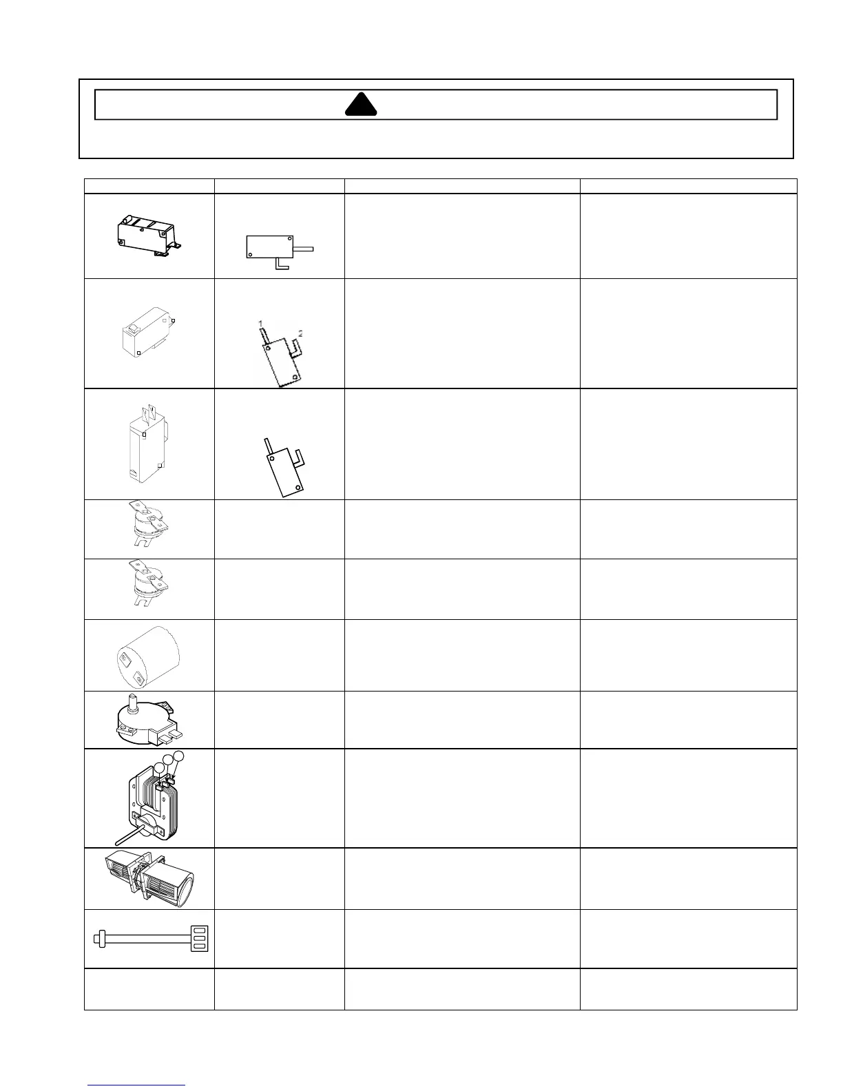
Illustration Component Test Procedure Results
Primary Interlock
Switch Test
(Top Switch)
1
2
Measure resistance between
terminals 1 and 2:
Door Open ...................................................
Door Closed.................................................
Open
Continuity
Secondary Interlock
Switch Test
(Bottom Switch)
Measure resistance between
terminals 1 and 2:
Door Open ...................................................
Door Closed.................................................
Open
Continuity
Interlock Monitor
Switch Test
(Middle Switch)
1
2
Measure resistance between
terminals 1 and 2:
Door Open ...................................................
Door Closed.................................................
Continuity
Open
Magnetron Thermal
Cut-Out (Thermostat)
Disconnect all wires from TCO.
Measure resistance across terminals.
Magnetron TCO ...........................................
Open at 302°F (150°C) and closed at
32°F (0°C)
Oven Thermal Cut-
Out (Thermostat)
Disconnect all wires from TCO.
Measure resistance across terminals.
Oven TCO....................................................
Open at 230°F (110°C)
Closed at 0°F (32°C)
Lamp receptacle Test continuity of receptacle terminals......... Indicates continuity if bulb is good and
installed.
Turntable Drive Motor
(Synchronous motor)
Measure voltage across terminals ...............
Measure resistance across terminals...........
Approximately 120 VAC
Approximately 2-4 Ω
A
B
C
Fan motor Remove all wires from motor.
Measure resistance .....................................
(All measurements approximate)
Across terminals A & C: 35-50 Ω
Across terminals A & B: 5-15 Ω
Infinite or several, motor is defective.
Ventilation Motor Remove all wires
Measure resistance across terminals...........
High Speed: Approximately 49-69 Ω
Low Speed: Approximately 97-117 Ω
Thermistor Remove connector from circuit board.
Measure resistance across pins 1 & 3 .........
Approximately 250-360 KΩ (70°F,
20°C ± 35°F, 2°C)
Refer to Parts Manual
for proper power cord
part number.
Power cord Measure resistance of wires ........................ Continuity on each wire.
Verify polarity and grounding.
 Loading...