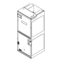
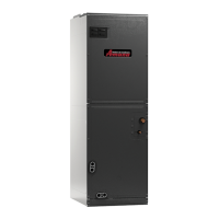
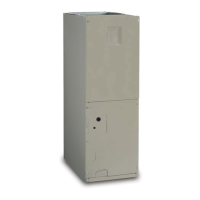
EasyManua.ls Logo

Maytag Amana AMVT P1400 Series User Manual

Maytag Amana AMVT P1400 Series
32 pages
To Next Page IconTo Next Page
Page #1 background imageLoading...
Page #1 background image
AMVT***P1400**
AIR HANDLERS INSTALLATION &
OPERATING INSTRUCTIONS
© 2022-2023 Daikin Comfort Technologies Manufacturing, L.P.
www.goodmanmfg.com - or - www.amana-hac.com
19001 Kermier Rd., Waller, TX 77484
P/N: IOG-4040B Date: February 2023
Contents
1 Important Safety Instructions .................................... 3
2 Shipping Inspection ................................................... 3
2.1 Parts ....................................................................... 3
2.2 Handling ................................................................. 3
2.3 Shipping Material Removal..................................... 3
3 Codes & Regulations ................................................. 3
4 Replacement Parts ..................................................... 3
5 Pre-Installation Considerations ............................... 3
5.1 Preparation ............................................................. 3
5.2 System Matches ..................................................... 3
5.3 Interconnecting Tubing ........................................... 3
5.4 Clearances ............................................................. 3
5.5 Horizontal Applications ........................................... 4
6 Installation Location ................................................... 4
 4
...................... 5
6.3 Horizontal Right Installation  ................... 5
6.4 Humid Environment Installations ............................ 5
6.4.1 All Installations – Humid Environments ............... 5
 5
6.4.1.3 Horizontal Installations – Humid Environments 5
7 Refrigerant Lines ........................................................ 6
7.1 Tubing Size ............................................................. 6
7.2 Tubing Preparation ................................................. 6
7.3 Tubing Connections ................................................ 7
7.4 Thermal Expansion Valve System Adjustment ....... 9
8 Condensate Drain Lines ........................................... 10
9 Ductwork .................................................................... 11
9.1 Return Ductwork .................................................... 11
10 Return Air Filters ..................................................... 11
11 Electric Heat ............................................................. 11
12 Electrical and Control Wiring ................................. 14
12.1 Building Electrical Service Inspection .................. 14
WARNING

This device, which was assembled by Daikin Comfort Technologies


FCC: FCC ID QOQBGM111. And this international radiator has an
Industry Canada ID: IC 5123A-BGM111.
This device complies with Part 15 of the FCC’s Rules. Operation of this
device is subject to two conditions:


interference that may cause undesirable operation.
And this device meets the applicable Industry Canada technical


Silicon Laboratories Finland Oy, which can be contacted by calling

The FCC responsible party is Daikin Comfort Technologies
Manufacturing, L.P. may be contacted by calling 713-861-2500, or at

This equipment complies with FCC radiation exposure limits. To ensure
compliance, human proximity to the antenna shall not be less than
20 cm during normal operations.
®
is a registered trademark of Maytag Corporation or its related companies and is used under license. All rights reserved.




























WARNING

Table of Contents

Questions and Answers:

Maytag Amana AMVT P1400 Series Specifications

General IconGeneral
SeriesAMVT P1400
ManufacturerMaytag Amana
Blower TypeVariable Speed
Motor TypeECM
Refrigerant TypeR-410A
Voltage208/230V
Phase1
Frequency60 Hz
TypeAir Handler
Cooling Capacity1.5 to 5 tons

Summary

Safety and General Information

Important Safety Instructions

Essential safety warnings and symbols for safe operation.

Electrical Safety Warnings

Critical warnings regarding high voltage and shock hazards.

Carbon Monoxide Poisoning Hazard

Risks and prevention measures for CO poisoning.

Installation and System Preparation

Shipping Inspection and Handling

Procedures for inspecting and handling unit upon delivery.

Codes, Regulations, and Parts

Compliance with codes and information on obtaining replacement parts.

Pre-Installation Considerations

Site preparation, system matches, and necessary clearances.

Installation Location and Orientation

Guidelines for unit placement, altitude, and installation methods.

Humid Environment Installation

Requirements for managing condensation in high humidity.

Refrigerant Line Installation

Proper installation of refrigerant tubing and connections.

Condensate Drain Line Installation

Ensuring proper drainage and preventing sweating.

Ductwork and Filter Requirements

Duct sizing, airflow, sealing, and filter installation.

System Configuration, Operation, and Electrical

Electric Heat Installation

Installing electric heat kits and understanding temperature rise.

Electrical and Control Wiring

Procedures for safe and correct electrical and low voltage wiring.

CoolCloud HVAC Application

Using the mobile app for setup, diagnostics, and updates.

Quick Start Guides

Initial setup for communicating and non-communicating units.

Dehumidification and Accessory Control

Features for dehumidification, alarms, and external accessories.

Ramping Profiles and Air Cleaner

Blower speed profiles and electric air cleaner connection.

Air Handler Display and Codes

Understanding the unit's display codes and system status.

Start-up, Troubleshooting, Maintenance, and Wiring

Thermal Expansion Valve (TXV) Adjustment

Adjusting the TXV for optimal superheat and system performance.

Start-Up Procedure

Essential steps before initial system operation.

Air Handler Troubleshooting Matrix

Identifying and resolving common operational faults and errors.

Homeowner Maintenance Recommendations

Routine checks and maintenance tasks for homeowners.

Start-Up Checklist

Final verification checklist before system operation.

Wiring Diagrams

Schematics for connecting electrical components and controls.

Related product manuals