Gl
HOW TO READ THE DIAGRAMS
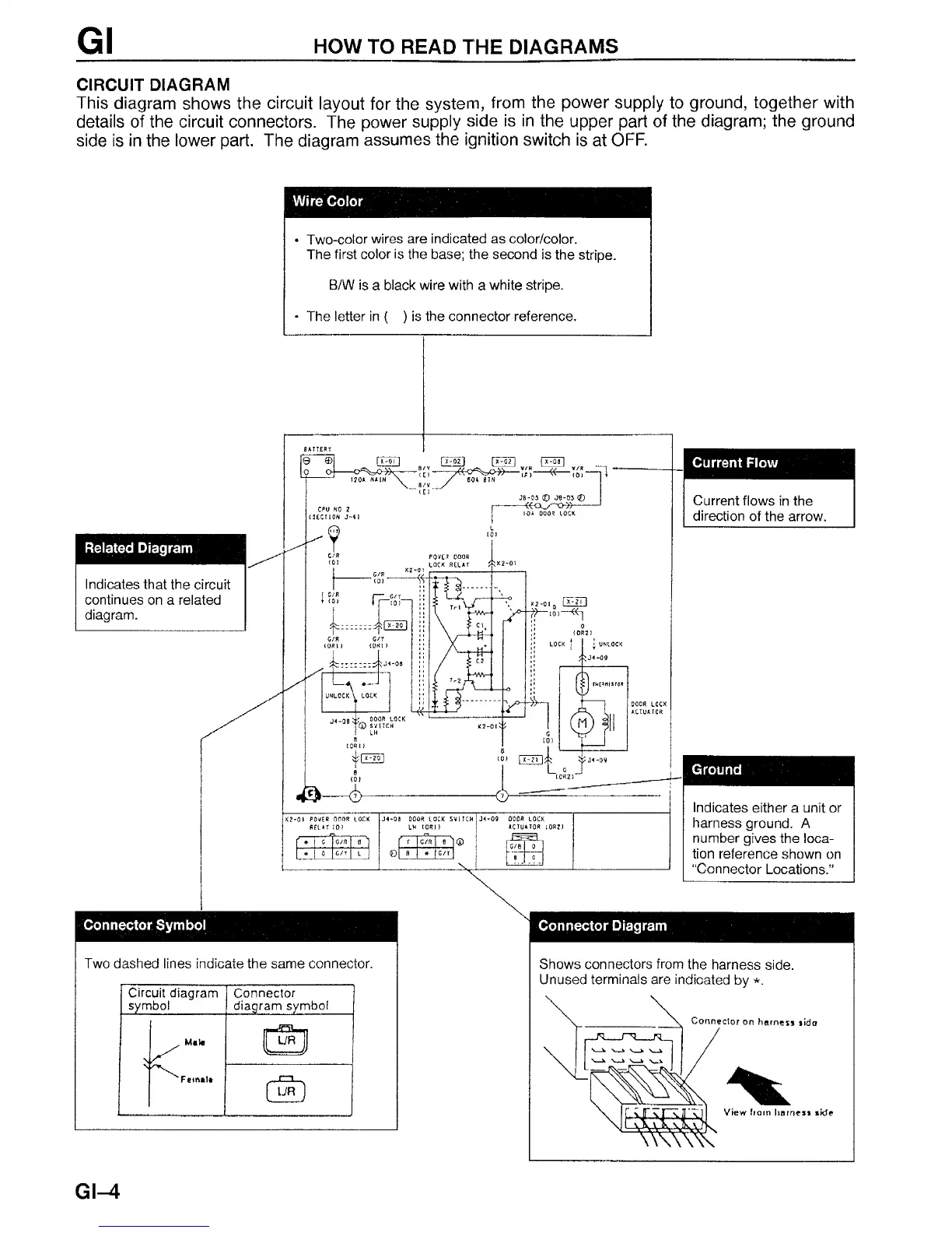
CIRCUIT DIAGRAM
This diagram shows the circuit layout for the system, from the power supply to ground, together with
details of the circuit connectors. The power supply side is in the upper part of the diagram; the ground
side is in the lower part. The diagram assumes the ignition switch is at OFF.
Wire Color
• Two-color wires are indicated as color/color.
The first color is the base; the second is the stripe.
B/W is a black wire with a white stripe.
• The letter in ( ) is the connector reference.
Related Diagram
Indicates that the circuit
continues on a related
diagram.
Current Flow
Current flows in the
direction of the arrow.
Ground
Indicates either a unit or
harness ground. A
number gives the loca
tion reference shown on
“Connector Locations.”
Connector Symbol
Two dashed lines indicate the same connector.
Circuit diagram
Connector
symbol diagram symbol
Mata
laiMrT-luwwn
r * n
Femala
Cm D
Connector Diagram
Shows connectors from the harness side.
Unused terminals are indicated by *.
Connector on harness sida
View from harness
GI-4


 To Next Page