Verify that the voltage of the instrument
cluster terminal 2U is 1.0V or less .
• If the voltage is as specified,
replace the instrument cluster.
• If the voltage is not as specified,
inspect the following parts:
Panel light control switch
Wiring harness
(Batterypanel light
control
switchinstrument
cluster)
2
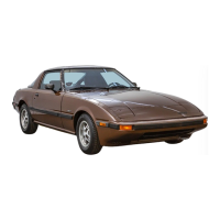
Turn the panel light control switch toward dark
until a click is heard.(Dimmer switch ON)
Input signal to the instrument cluster is
normal.
DATA MONITORING AND RECORDING PROCEDURE
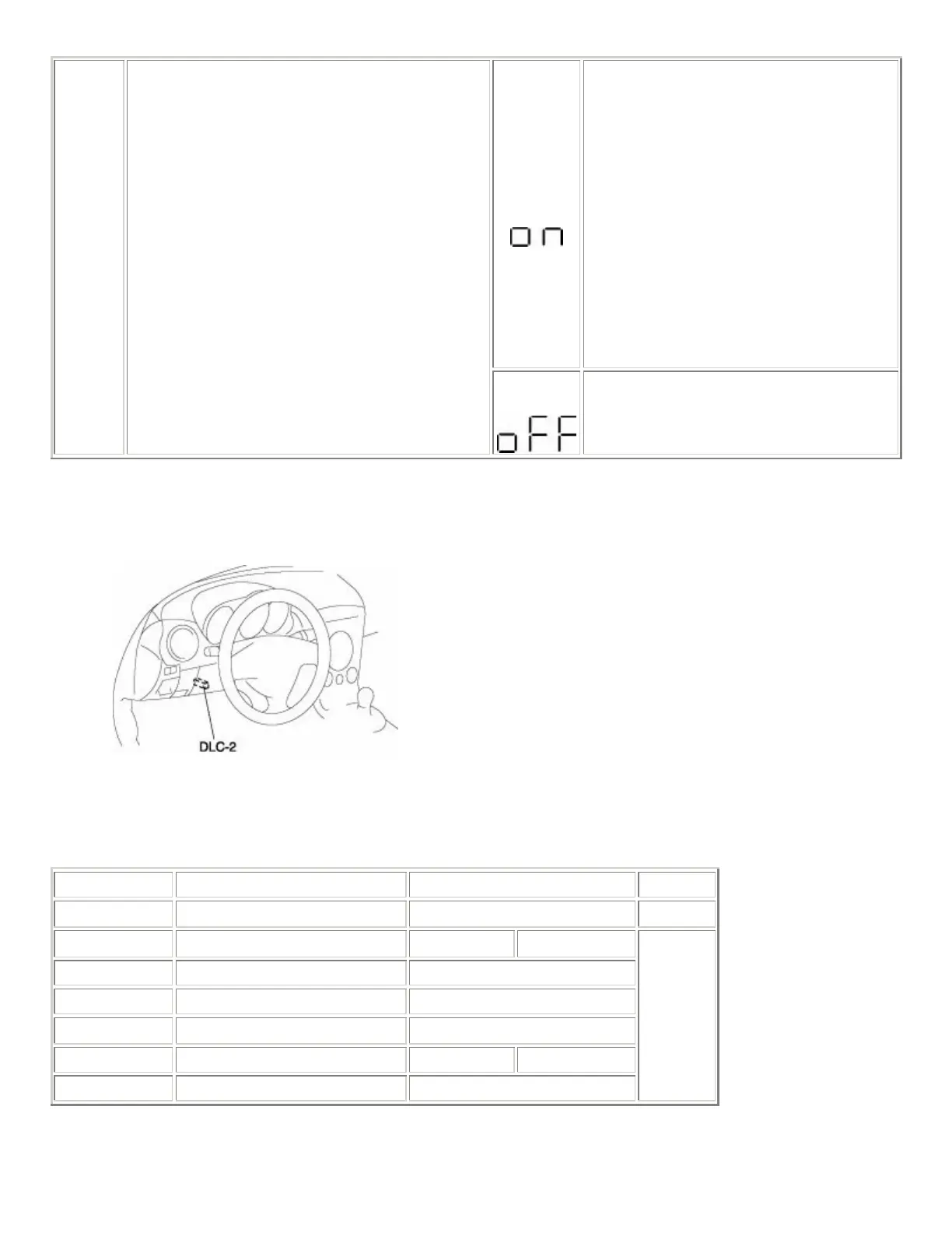
1. Connect the WDS or equivalent to the diagnostic connector 2 (16-pin).
2. Verify the data monitor items.
Indication Item Table
Monitor item Input-output signal/part name Unit/State Terminal
CCNT_HE DTC Number of continuous DTCs
ECT_GAUGE Water temperature gauge
°F °C
FUEL Fuel flow rate l/min
ODO COUNT Odometer m
OPSC Oil pressure gauge
SPEEDSG Speedometer mph km/h
rpm Tachometer rpm
1J, 1L
 Loading...