Do you have a question about the MB QUART MBQX-STG5-1 and is the answer not in the manual?
Locate installation videos for specific vehicle products on the MB Quart website.
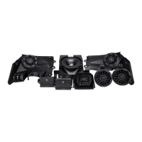
List of all components included in the MBQX-STG5-1 audio system package.
Details on the one-year warranty, proof of purchase, and serial number requirements.
Information on accessing FAQs, tips, and contacting technical support via email.
The estimated time required to complete the installation process.
A comprehensive list of tools and supplies necessary for the installation.
Essential safety measures to ensure a safe installation process.
Steps for preparing components and vehicle before beginning disassembly.
Instructions for removing vehicle seats and disconnecting the battery.
Instructions for removing the driver, passenger, and center console side panels.
Steps to remove hardware and retaining clips from the center dash area.
Procedure for removing the passenger and driver side top dash panels.
Instructions for removing the inner cover of the vehicle's center console.
Steps to prepare and identify all wiring harnesses before routing.
Details on the wiring for optional illuminated speaker rings.
Locate bus bar and connect system power, ground, and accessory wires.
Route rear speaker harness and other system wiring to their locations.
Prepare power plug and route source unit wiring and RCA cables.
Make source unit wire connections and seal with heat shrink.
Identify and drill mounting holes for the source unit housing.
Mount amplifiers and set initial crossover and level adjustments.
Test fit the amplifier plate and drill mounting holes.
Mount the amplifier plate and connect audio/power wiring.
Prepare and load the main subwoofer enclosure under the driver's seat.
Attach mounting brackets to the subwoofer enclosure and seat mounts.
Connect the main subwoofer enclosure's wiring pigtail.
Install the second subwoofer amplifier and set initial filters and levels.
Route and connect power, speaker, and RCA wiring for the second amplifier.
Prepare and load the optional subwoofer enclosure under the passenger seat.
Attach mounting brackets and connect wiring for the optional subwoofer.
Connect rear speaker harness and route wiring to speaker locations.
Remove roll cage covers and speaker pod clamps for installation.
Place spacer and secure rear speaker pod clamps to the roll cage.
Adjust speaker pod swivel base and make speaker/illumination wiring connections.
Cover wiring connections with tape and replace cover panel.
Instructions for using the extension harness on four-seat models.
Prepare front speaker panels by removing and replacing clip retainers.
Connect speaker, install passenger side panel, and check fit.
Secure front speaker panel and note fitment for aftermarket roll cages.
Replace original switches and attach Smart-Lok module to new dash panel.
Connect driver's side speaker and temporarily set the panel.
Review all installation steps to ensure correct connections.
Initial crossover, level, and filter settings for the NA2-400.2 amplifier.
Initial boost, level, LPF, and subsonic filter settings for the NA2-400.1 amplifier.
Reconnect the battery and connect source unit's electrical and RCA cables.
Insert the main fuse and turn the ignition to ACC position.
Verify power, inputs, Bluetooth, AM/FM, speaker output, and balance.
Adjust gain to match source output and set crossover frequencies.
Adjust Low Pass, High Pass, Subsonic filters and Boost switch.
Ensure amplifier gain matches signal output without distortion.
Reassemble speaker panels, dash components, and console covers.
Secure main harness, reinstall console covers and source unit housing.
Reinstall seats, ensure all hardware is secured, and no parts are left.
Check battery charge, terminal security, and harness connections.
Ensure all dash panels, speaker panels, and pods are fitted securely.
Verify seat movement and ensure no original hardware is missing.
Diagram illustrating the complete wiring harness layout, including optional components.
Space for recording serial numbers, final settings, and installation details.
| Brand | MB QUART |
|---|---|
| Model | MBQX-STG5-1 |
| Category | Stereo System |
| Language | English |