31
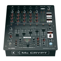
Connection and control elements
(23) TIME OFFSET display
This display shows the synchronisation of CROSSFADER channels A and B. If the centre LED lights up, both pie-
ces of music are synchronous. If one of the LEDs on the left or the right lights up, the pieces of music are not syn-
chronous.
The TIME OFFSET display only lights up if the SYNC LOCK function has been activated for
both channels (A and B).
(24) TEMPO DIFFERENCE display
The 9-character TEMPO DIFFERENCE display shows the tempo difference of the two CROSSFADER channels
A and B. If the centre LED lights up, both pieces of music have the same tempo. If one of the LEDs on the left or
the right lights up, the pieces of music do not have the same tempo.
The TEMPO DIFFERENCE display only lights up if the SYNC LOCK function has been activa-
ted for both channels (ASSIGN A and B).
(25) KILL A and B
Use these buttons to fade out treble (HI), mids (MID) or MASS (LOW) from both crossfader channels. When the
switch is activated, the corresponding LED lights up.
If all KILL buttons of a channel are pressed, the complete signal is suppressed. No music signal
is played.
(26) CF CURVE control
Use the CF CURVE control to change the control characteristics of the CROSSFADER (22). Turn the control to
the right. The two channels are faded in or out only at the end of the control range (logarithmical). Turn the con-
trol to the left. The two channels are faded in or out continuously over the whole control range (linear).
(27) XPQ SURROUND control
Use this control to set the intensity of the XPQ SURROUND effect.
(28) XPQ ON switch
Press the XPQ ON switch to activate the SURROUND function. When the SURROUND function is active, the
SURROUND LED lights up. The output signal (MASTER and BOOTH) appears more lively and fresh due to the
broadening of the signal.
(29) BPM channel LEDs
The LEDs indicate which of the four input channels CH1 - CH4 are assigned to the BPM counter. Use the
CROSSFADER ASSIGN A and B switch (21) to make the selection.