3-- 6
© 2012 Mobile Climate Control T-299 Rev. 08/2012
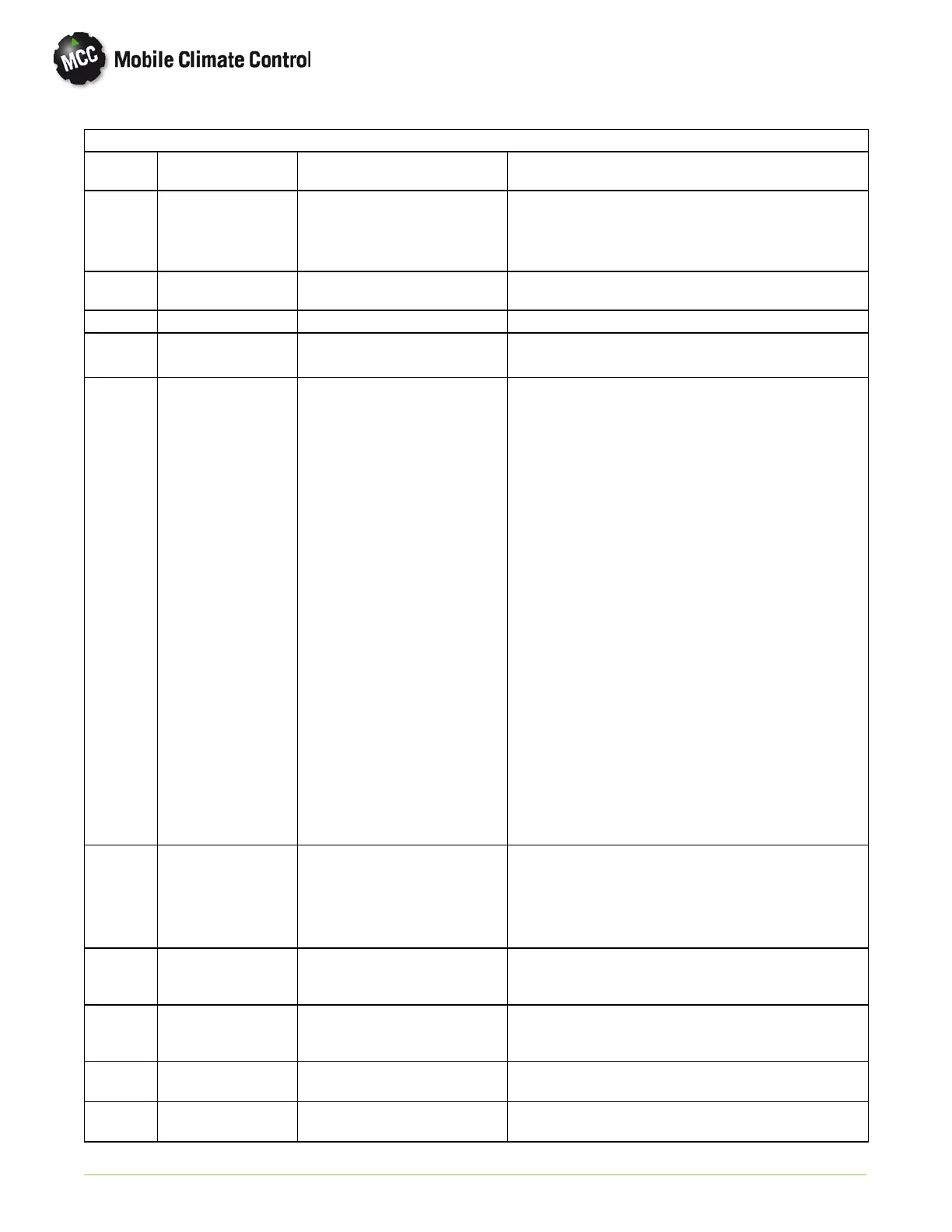
Table 3-5 TROUBLESHOOTING ALARM CODES (TOTAL CONTROL)
ALARM
CODE
TITLE CAUSE REMEDY
AL 13 Return air sensor. Open circuit or short circuit on
the return air sensor connec
tion.
Check connections on RAS + and RAS - on the control
board. Make sure the Red terminal is connected to RAS
+ and Black terminal is connected to RAS - on the con
trol board.
AL 15 Set point out of
range
Wrong set point is saved on the
controller.
Controller will correct this problem automatically.
AL 17 Not Used
AL 21 Low Voltage Controller senses battery volt
ageislessthan10volts.
Check battery voltage.
AL 27 Compressor 1 pres
sure alarm
Open or short circuit in the
clutch related circuit (CLHR on
the control board) such as:
High pressure switch open cir
cuit.
Low pressure switch open cir
cuit, if the low pressure switch
is in series with the high pres
sure switch in the condenser.
Wire from controller CLHR to
terminal 3 on the electrical pan
el terminal board is open.
Wire from terminal 3 to con
denser is open, short to ground
or short to battery.
Wire from terminal 2 to clutch
is open, short to ground or
short to battery.
Wire from clutch to ground is
open.
Clutch coil open or short cir
cuit.
Turn off the controller by pressing OFF button.
Measure the resistance between terminal 3 and terminal
2 on the electrical panel. The reading should be less than
1 OHM. This is to check the pressure switch circuit. If
the resistance is too high, look for open circuit on the
high pressure or low pressure switches.
Measure the resistance between terminal 2 to g round.
The readings should be about 6 OHM. This is to check
the clutch coil. If readings are low, look for a open cir
cuit in the clutch coil.
Check with power on:
Connect voltmeter to terminal 3 and ground. Press the
ON button on the controller and wait for 10 seconds. If
you see 12 VDC appear for about 1second and disap
pears, the circuit from CLHR on control board to termi
nal 3 is good but circuit from terminal 3 to clutch is
open.
Connect voltmeter to terminal 2 and ground. Turn on
controller by pressing the ON button. Wait for about 10
seconds. If you see 12 VDC appear for 1 second and
disappear, the circuit from CLHR on control to terminal
2 is good but the circuit from terminal 2 to clutch is
open.
If the 12 VDC does not appear, then the pressure switch
circuit is open. Follow the procedure mentioned above
for tracing the pressure switch circui t.
AL 41 Compressor 2 pres
sure alarm
Open circuit on compressor 2
high pressure circuit.
If the second compressor is used follow the procedure for
Alarm 27.
If the second compressor is not used, there should be a
jumper wire between HP2 + and HP - on the control board
inputs.
AL 43 Condenser fan relay
malfunction
Short circuit between CFM
+ and CFM -- on the control
board.
Check condenser fan relay CR and its related cir-
cuit.
AL 44 Evaporator fan relay
malfunction
Short circuit between EFM +
and EFM -- on the control
board.
Check evaporator fan relay HSR and the related
circuits.
AL 45 Clutch Relay
malfunction
Malfunction is detected on
the CLR output.
AL 46 EFS Control
malfunction
Malfunction is detected on
the EFS output.
 Loading...
