4-- 2© 2012 Mobile Climate Control T-299 Rev. 08/2012
4.2 MAINTENANCE PROCEDURES
The following air conditioning service equipment is
required in order to properly perform the
maintenance procedures.
1.. Manifold Gauge Set MCC P/N 07-00294-00
Provides access to and m o nitors pressures within the
system. Manifold gauge sets are available in different
configurations and styles. 3-way or 4-way, liquid
filled gauges, with or without a sight glass, 3 hoses or
4 hoses, 1/4 inch or 3/8 inch manifold connections,
etc. Familiarize yourself with the proper operation of
your manifold gauge set before attempting any
service.
2.. R134a Low Side (Suction) Coupler MCC P/N
07-00307-04 - Connects the air conditioning system
Suction Access Port to the Manifold G auge Set.
3.. R134a High Side (Discharge) Coupler MCC
P/N 07-00307-05 - Connects the air conditioning
system Discharge Access Port to the Manifold
Gauge Set.
4.. Vacuum Pump - 2 Stage (5 CFM Minimum)
MCC P/N 07-00176-11 - Removes moisture and air
from the air conditioning system in order to obtain
required micron level.
5.. Micron Gauge, Digital MCC P/N 07-00414-00
Monitors the evacuatio n process in units of microns.
Micron gauges can be either digital (electronic) or
analog.
6.. Recovery/Recycle Machine (R134a) MCC
P/N MVS-115-F-L-CT (115VDC),
MVS-240-F-L-CT (240 VDC) - Recovers and
recycles R134a refrigerant that is present within the
air conditioning system.
7.. Refrigerant Scale MCC P/N 07-00315-00 -
Accurately weighs the transfer of refrigerant into the
air-conditioning system.
8.. Refrigerant Cylinder - Storage tank for R134a.
9.. Heat Blanket - Used to increase internal
temperature of th e refrigerant cylinder, greatly
increasing the transfer of refrigerant to th e air
conditioning system.
10.. Oil Injector - Used to add additional amount s of
oil to a closed system.
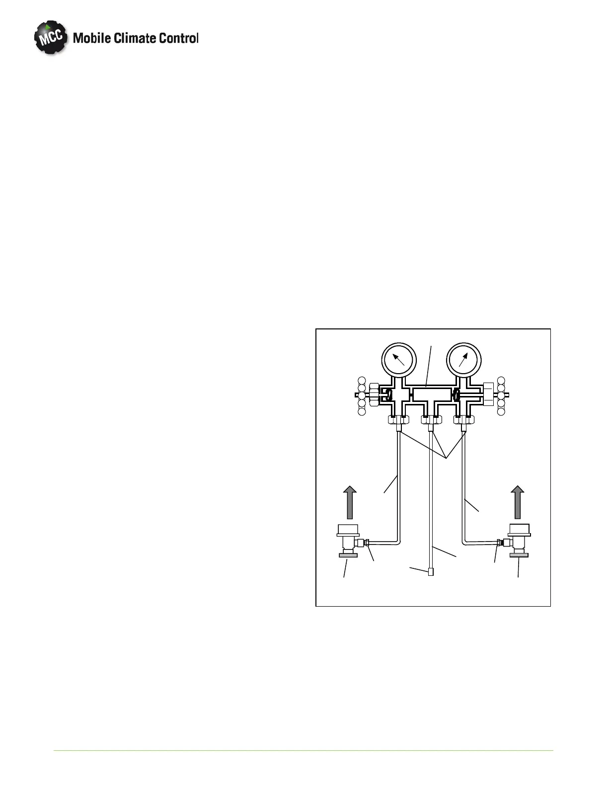
4.3 INSTALLING MANIFOLD GAUGES
The manifold gauge set (see Figure 4-1) is used to
determine system operating pressures, add
refrigerant charge, and to equalize or evacuate the
system.
When the suction pressure hand valve is frontseated
(turned all the way in), the suction (low) pressure can
be checked. When the discharge pressure hand valve
is frontseated, the discharge (high) p ressure can be
checked. When both valves are open (turn ed
counter-clockwise all the way out), high pressure
vapor will flow into the low side. When the suction
pressure valve is open and the discharge pressure
valve shut, the system can be charged.
A R-134a manifold gauge/hose set with self-sealing
hoses is required for service of the models covered
within this manual. The manifold gauge/hose set is
available from Mobile Climate Control. (Mobile
Climate Control P/N 07-00294-00, which includes
items 1 through 6, Figure 4-1 .) To perform service
using the manifold gage/hose set, do the following:
OPENED
(Backseated )
HAND VALVE
CLOSED
(Frontseated)
HAND VALVE
SUCTION
PRESSURE
GAUGE
DISCHARGE
PRESSURE
GAUGE
To Low Side
Access Valve
To High Side
Access Valve
Red Knob
Blue Knob
1.
4.
3.
YELLOW
2.
4.
5.
6.
3.
RED
3.
BLUE
2.
1.. Manifold Gauge Set
2.. Hose Fitting (0.5-16 Acme)
3.. Refrigeration and/or Evacuati on Hose
. (SAE J2196/R-134a)
4.. Hose Fitting w/O-ring (M14 x 1.5)
5.. High Side Field Service Coupling
6.. Low Side Field Service Coupling
Figure 4-1 Manifold Gauge Set
 Loading...
