4-- 17© 2012 Mobile Climate Control T-299 Rev. 08/2012
b. Connect an ohmmeter across switch terminals.
If the switch is good, the ohmmeter will indicate
no resistance, indicating that the contacts are
closed.
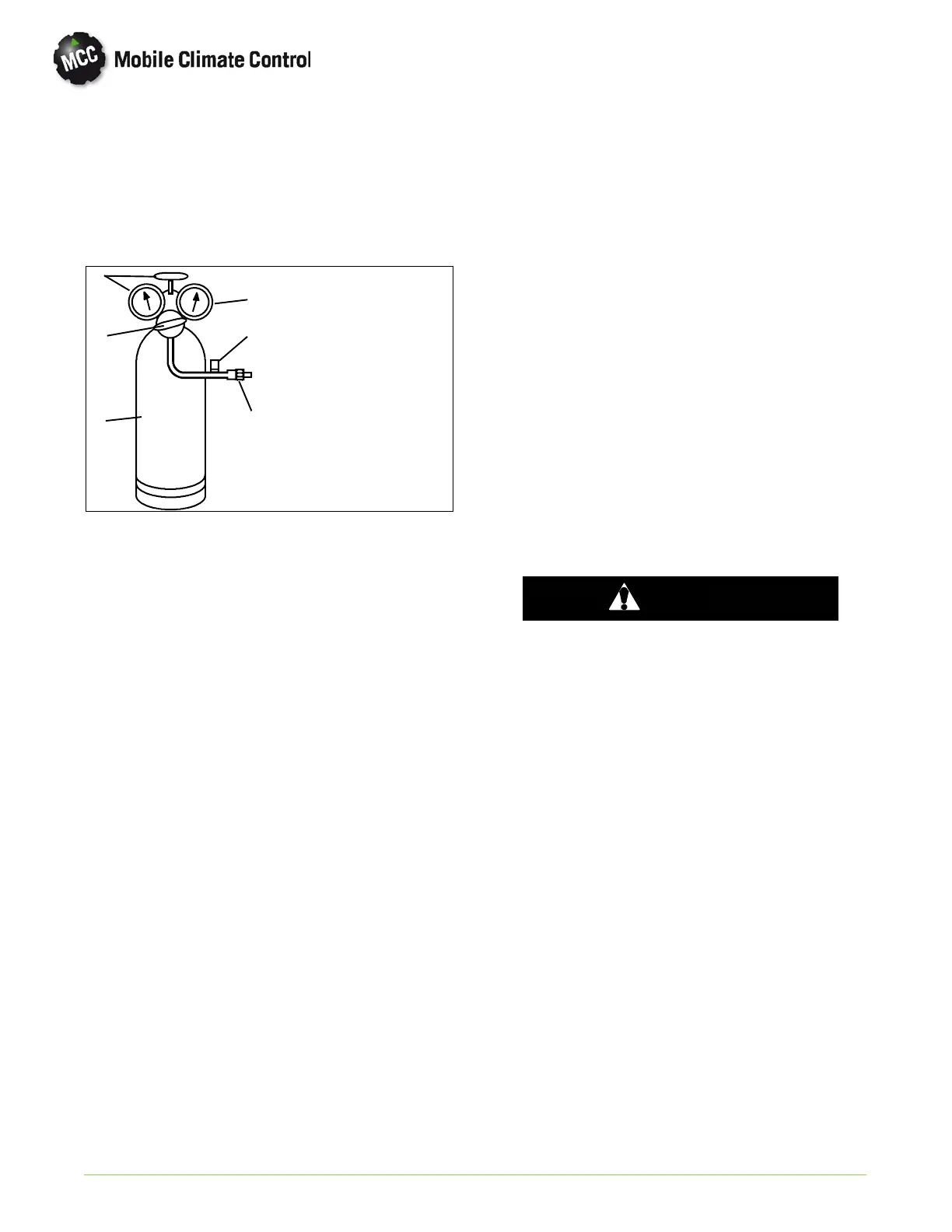
c. Con n ect switch to a cylinder of dry nitrogen. (See
Figure 4-9.
1. Cylinder Valve
and Gauge
2. Pressure
Regulator
3. Nitrogen Cylinder
4. Pressure Gauge
(0 to 400 psig =
0to36kg/cm@)
5. Bleed-Off Valve
6. 1/4 inch
Connection
1
2
3
4
5
6
Figure 4-9. Checking High Pressure Switch
d. Set n itrogen pressure regulator higher than
cutout p o int on switch being tested.(Refer to
paragraph 1.7)
e. Open cylinder valve. Slowly open the regulator
valve to increase the pressure until it reaches
cutout point. The switch should open, which is
indicated by an infinite reading on an ohmmeter
(no continuity).
f. Close cylinder valve and release p ressure th rou gh
the b leed-off valve. As pressure dro p s to cut-in
point, the switch contacts should close,
indicating no resistance (continuity) on the
ohmmeter.
g. Replace switch if it does not function as outlined
above.
4.19 MOISTURE INDICATOR (SYSTEM)
There are two types of m o isture indicators presently
in use with Mobile Climate Control systems.
1. Green/Yellow (Previous Configuration)
Green = Dry System Yellow = Wet System
2. Blue/Pink (Current Configuration)
Blue=Dry Pink=Wet
4.20 FILTER-DRIER OR RECEIVER-DRIER
Mobile Climate Control condensers are supplier with
either a filter-drier or a receiver-drier.
NOTE
All microchannel condenser assemblies are
equipped with a receiver-drier with an
integral high pressure switch.
If a pressure drop across the Filter-Drier (see
Figure 4-10) or Receiver-Drier (see Figure 4-11) is
indicated or the moisture-indicator shows an
abnormal (wet) condition, the Filter-Drier or
Receiver-Drier must be changed.
a. Check for a restricted filter by touching the filter
drier or r eceiver-drier on inlet and o utlet
connections. If there is a noticeable temperature
difference the filter is probably restricted and
should be replaced.
b. Recover refrigerant, r efer to paragraph 4.4.
c. Place a new filter-drier or receiver-drier near the
unit for immediate installation.
d. Using two open end wrenches, slowly crackopen
and remove the liquid line O-ring fittings on each
side o f the filter-drier.
WARNING
The filter-drier or receiver-drier may contain
liquid refrigerant. Slowly open the fitting
nuts and avoid contact with exposed skin or
eyes.
e. Loo sen the hose clamp(s) securing the filter drier
or receiver-drier to the condenser assembly.
f. Remove the filter-drier o r receiver drier.
Transfer high pressure switch if required.
g. Remove seal caps from the new filter-drier or
receiver-drier. Ap p ly a light coat of mineral o il to
the fittings and O'rings.
h. Assemble the new filter-drier or receiver-drier to
the liquid lines ensuring that the arrow on the
body of t he filter-drier o r receiver-drier po ints in
the direction of the refrigerant flow (liquid
refrigerant flows from the condenser to the
evaporator). Finger tighten the liquid line
fittings.
i. Tighten filter-drier or receiver-drier O-ring
fittings using two open end wrenches. Refer to
paragraph 4.10 for torque specifications.
j. Evacuate system to 500 microns by connecting a
vacuum pump as shown in Figure 4-2.
k. Charge system according to paragraph 4.8.2.
 Loading...
